

Viscosity measurement is harder than density measurement. With density, you have one number. With viscosity, you have a relationship between shear stress and shear rate — and if the process conditions change that relationship, the reading changes even when nothing is wrong with the instrument.
The first step in troubleshooting a viscosity meter is to decide whether the problem is the instrument or the process. That decision is not always obvious with viscosity, because a genuine process change can look exactly like an instrument failure.
This guide is organized by symptom. For each symptom, the likely causes are ranked by probability, and the diagnostic checks are specific enough to isolate the root cause without unnecessary disassembly.
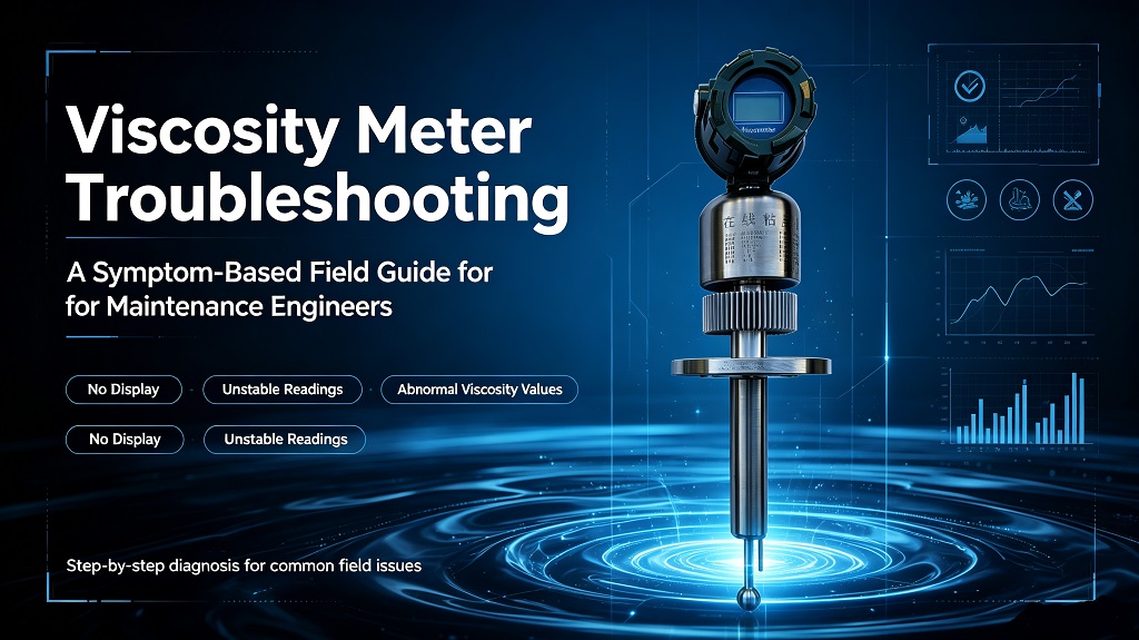
Symptom 1: Viscosity reading fluctuates by more than ±5%
Cause 1: Non-homogeneous fluid.
This is the most common cause of viscosity fluctuation in production processes. If the fluid is not thoroughly mixed at the sampling point, the viscosity reading will vary depending on the composition of the sample that reaches the sensor.
Check: Is the mixing upstream of the sensor adequate? Is the sampling point representative of the process? If the product is a blend of multiple components, is each component being added consistently? Take a physical sample and measure viscosity in the lab. If the lab measurement is also fluctuating, the problem is process homogeneity, not the meter.
Cause 2: Temperature fluctuation at the sensor.
Viscosity is exponentially temperature-dependent. A 2°C change in temperature can produce a 10–20% change in viscosity for high-viscosity fluids. If the process temperature is oscillating, the viscosity reading will oscillate with it — not because the fluid composition changed, but because the temperature changed.
Check: Monitor the temperature signal from the viscometer (or from a separate temperature sensor). If the temperature is fluctuating, the viscosity fluctuation follows from the temperature fluctuation. Fix the temperature control upstream. Do not try to fix a temperature problem in the viscosity signal — it is the wrong place to solve it.
Cause 3: Bubbles or gas entrainment.
Entrained gas bubbles change the effective density and apparent viscosity of the fluid. For rotational viscometers, gas bubbles can also affect the torque reading directly. For vibrational viscometers, entrained gas dampens the vibration and produces a lower apparent viscosity.
Check: Look at the fluid at the sampling point. Is there visible aeration? Is the pump upstream creating a vortex or drawing air? Eliminate the source of aeration. Install a deaeration section upstream of the sensor.
Cause 4: Sensor vibration frequency shift from coating.
A coating on the vibrational viscometer sensor changes the effective mass of the vibrating element. The frequency shifts. The meter compensates, but if the coating is uneven or building up unevenly, the frequency will fluctuate.
Check: Remove the sensor and inspect. If there is visible coating, clean with the appropriate solvent. Check the frequency reading in the diagnostics before and after cleaning.
| Viscosity fluctuation: diagnostic checklist
☐ Homogeneity: Take a physical sample. Is the lab viscosity also fluctuating? ☐ Temperature: Monitor T-signal. Is the temperature oscillating? ☐ Aeration: Look for bubbles at the sampling point. Check for vortex at pump suction. ☐ Sensor coating: Remove sensor, inspect fork or rod for buildup. ☐ Flow velocity: Is the flow stable? A pulsing flow creates pulsing shear.
Key distinction: Temperature changes cause viscosity changes. If T is stable but viscosity is fluctuating, the problem is in the fluid (homogeneity, aeration). If T is fluctuating, fix the temperature control first. |
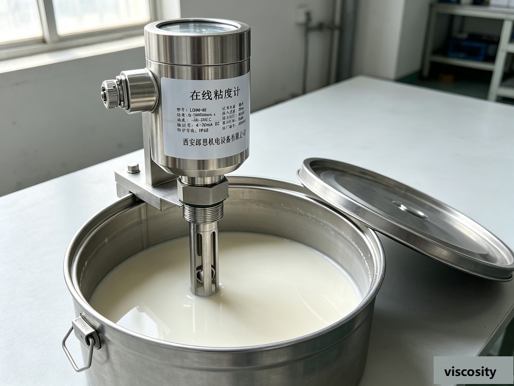
Symptom 2: Reading is consistently off by more than 10%
Cause 1: Shear rate mismatch.
For non-Newtonian fluids, viscosity changes with shear rate. If the viscometer operates at a different shear rate than the relevant process condition, the measured viscosity will not match the viscosity at the process shear rate.
Check: Determine the shear rate at the relevant process condition. Compare it to the effective shear rate of the viscometer. If they differ significantly, use a viscometer with an adjustable or documented shear rate. Alternatively, establish a correlation between the viscometer reading and the process performance parameter (e.g., pump power draw, spray quality).
Cause 2: Incorrect calibration.
Viscosity calibration standards are specific to the fluid type used. A calibration done in silicone oil standard is valid for Newtonian fluids. If the process fluid is non-Newtonian, the calibration does not transfer.
Check: Verify the calibration using a standard fluid of known viscosity in the same viscosity range as the process fluid. If you cannot obtain a traceable standard, compare the inline reading against a lab rotational viscometer using a physical sample from the process.
Cause 3: Sensor geometry changed.
For rotational viscometers, the gap between the bob and the cup must be exact. If the bob is worn, corroded, or deformed, the gap changes and the calibration is invalid. For vibrational viscometers, physical damage to the fork or rod changes the spring constant.
Check: Inspect the sensor geometry. For rotational viscometers, measure the bob diameter and compare to the specification. For vibrational viscometers, check the frequency with the sensor in air (should match the factory value). Any significant deviation indicates physical damage.
Cause 4: Process fluid properties have changed.
This is not an instrument problem. If the raw material changed (different base oil, different polymer batch, different solvent batch), the viscosity may change at the same temperature and composition. The meter is correctly reading the changed viscosity.
Check: Take a lab sample and confirm the viscosity. If the lab confirms the new viscosity, the inline meter is working correctly and the process material has changed. Update the setpoint or alert threshold accordingly.
Symptom 3: No output or a stuck reading
Cause 1: Viscosity out of sensor range.
Every viscometer has a viscosity range. Below the minimum, the signal-to-noise ratio is too low. Above the maximum, the damping is too high or the drive power is insufficient. In both cases, the output goes to a fault condition or reads at the limit.
Check: Check the process viscosity against the sensor specification. If the viscosity is above the maximum range, the meter is overloaded. If it is below the minimum, the signal is too noisy. Either way, you need a different range sensor.
Cause 2: Solidification or gelling in the sensor.
Some fluids solidify at low temperatures or upon standing. If the process stops and the sensor cools, the fluid can solidify around the sensor elements. The sensor cannot measure viscosity of a solid.
Check: Check the sensor temperature. If the temperature has dropped below the pour point or gel point of the fluid, the sensor is blocked. Heat the sensor and flush with a compatible solvent. Prevent recurrence by maintaining minimum process temperature above the pour point.
Cause 3: Electronics failure.
Power supply failure, failed drive circuit, or failed signal processing. Most modern viscometers have a diagnostic output that indicates the instrument status.
Check: Verify power supply. Check the diagnostic output (status word, fault code, drive current). If no diagnostic is accessible, check the drive frequency in the configuration software. A reading of 0 Hz or an extreme frequency indicates electronics failure.
Cause 4: Sensor mechanically stuck.
For rotational viscometers, the bob can get stuck against the cup wall if the bearing wears or if solid debris gets into the gap.
Symptom 4: Reading responds too slowly to process changes
Cause 1: Excessive damping or averaging time.
Most viscometers have configurable damping. If it is set too high, genuine process changes take too long to appear in the output.
Check: Reduce the damping time constant. Start at 1 second and increase until the output is stable without lag. For blending control, the response time should be fast enough to close the loop.
Cause 2: Thermal lag in the sensor.
If the process temperature changes, the sensor takes time to reach the new temperature. Viscosity is exponentially temperature-dependent, so thermal lag directly translates to viscosity lag.
Check: Check if the temperature signal is also lagging. If temperature lags, the viscosity lag follows from it. Use a sensor with a faster temperature response, or reduce the thermal mass around the sensor.
Cause 3: Sample transport delay.
If the viscometer is on a bypass loop with a long residence time, the reading will lag the actual process condition by the residence time of the bypass.
Check: Calculate the bypass residence time. Measure the distance from the process tap to the sensor and divide by the bypass flow velocity. If the residence time exceeds the desired response time, increase the bypass flow rate or move the sensor closer to the process tap.
Preventive maintenance schedule
| Interval | Task | What to Look For |
| Monthly | Compare inline reading to lab sample | Drift >10% = investigate calibration or process change |
| Monthly | Check temperature reading against reference | T error >1°C affects viscosity accuracy |
| Quarterly | Inspect and clean sensor | Coating, fouling, wear on bob/cup gap |
| Quarterly | Verify sensor frequency / drive current | Compare to factory baseline values |
| Annually | Full calibration with traceable standard | Use standard fluid in same viscosity range as process |
| Every 2 years | Replace sensor O-rings and seals | Check for degradation, hardening, leaks |
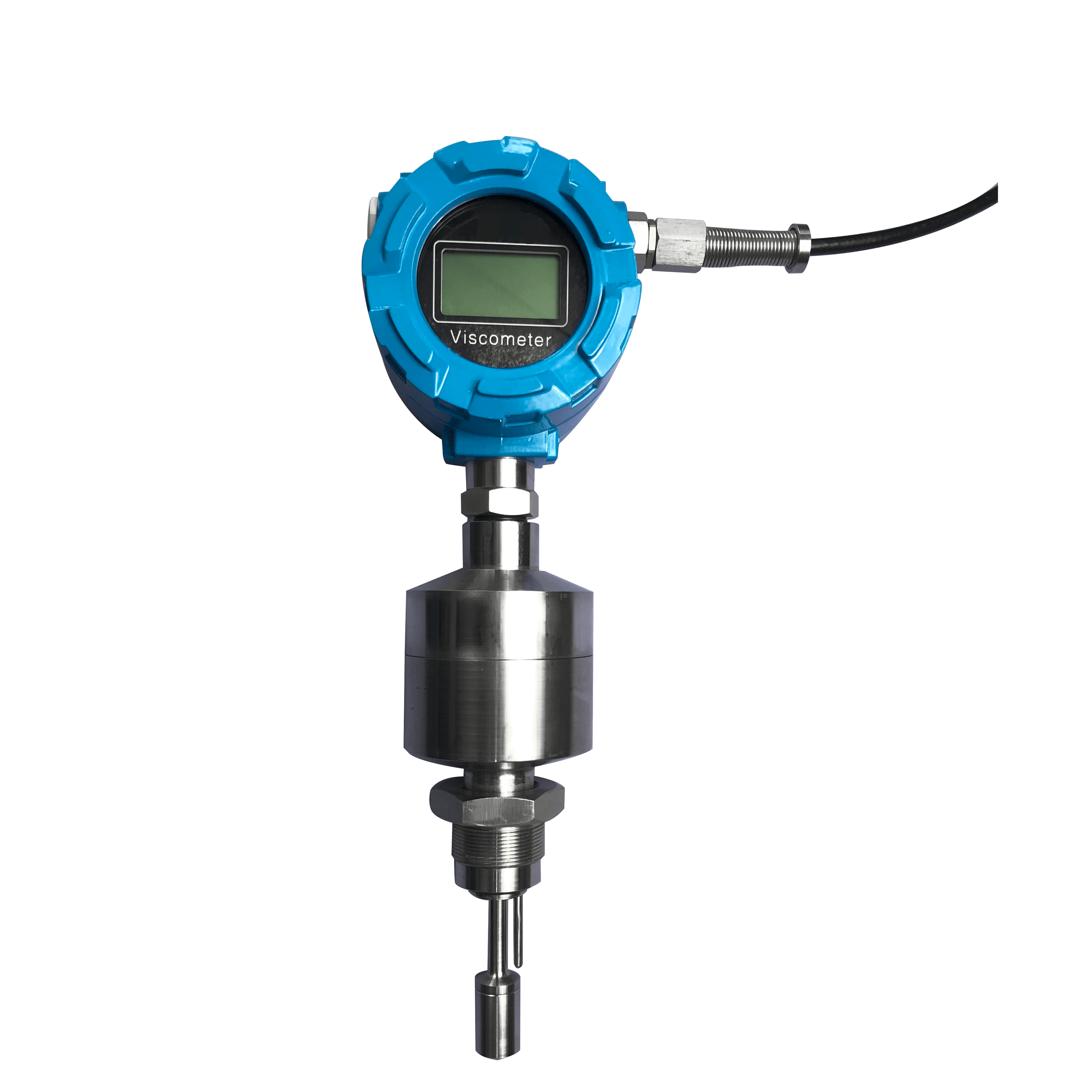
Common questions on viscosity meter troubleshooting
Why does viscosity reading change when I change the measurement shear rate?
Because the fluid is non-Newtonian. Viscosity is not a constant — it is a function of shear rate. Shear-thinning fluids (most paints, polymers, slurries) have lower viscosity at higher shear rates. If you change the viscometer spindle speed or the vibrational frequency, you change the shear rate, and you get a different viscosity. This is not an error — it is the correct behavior of the fluid. Use the shear rate that is relevant to your process.
Can I use a viscosity standard to check the calibration in the field?
Yes, but the standard must match the fluid type. A Newtonian viscosity standard (silicone oil) is valid for verifying the calibration of a Newtonian fluid process. It is not valid for verifying calibration of a non-Newtonian fluid process. For non-Newtonian processes, the field check is a comparison with a lab rotational viscometer using a physical process sample.
What is the maximum viscosity a tuning fork viscometer can handle?
The practical maximum for inline tuning fork viscometers is typically 5,000–10,000 mPa·s (cP), depending on the sensor design and the drive power available. Above this range, the damping is too high for reliable measurement. For higher viscosities, use a rotational viscometer or a capillary viscometer. LONNMETER LONN-V100 is rated to 5,000 mPa·s in standard configuration.
Why does the viscosity reading differ between the inline meter and the lab viscometer?
Three main reasons, in order of probability: (1) Different shear rate — the inline sensor measures at a different shear rate than the lab instrument. (2) Temperature difference — the lab sample has cooled or warmed relative to the process fluid. (3) Non-Newtonian behavior — the fluid structure changes between the process and the lab (shear history, temperature history). Establish a correlation under process conditions and use that correlation, not the lab reading, as the reference.
How do I clean a fouled vibrational viscometer sensor?
Use the appropriate solvent for the fouling material. Water-based fouling: flush with demineralized water, then isopropyl alcohol. Oil-based fouling: flush with a compatible solvent (check material compatibility). Polymer or resin fouling: may require a specific solvent or soaking. Do not use mechanical tools (scrapers, brushes) on the fork tines. After cleaning, verify the frequency in air matches the factory specification. Recalibrate after cleaning.
Post time: Sep-01-2026


