

Pick the wrong level technology and you will be climbing the tank again in six months, this time with a calibration laptop and a maintenance work order instead of a tape measure. We build both ultrasonic and radar level meters on the same production floor, calibrate them against the same traceable benches, and we still see specifiers lose the choice on the second line of the datasheet rather than the first. This guide is the internal conversation we have before a quote leaves the building: here is how the two technologies actually behave in the field, where each one quietly fails, and how to choose without guessing.
Two sensors, one job, different physics
Both instruments report the distance from a fixed point on top of the tank down to the liquid surface, then convert that distance into a level. Past that shared purpose the physics diverges completely.
An ultrasonic level meter sends a burst of sound down through the air space and listens for the echo bouncing off the liquid. It times the round trip and divides by the speed of sound. A radar level meter sends a microwave, times its round trip, and divides by the speed of light. One rides on pressure waves in the vapour gap; the other rides on electromagnetic waves that barely notice what is in that gap. That single difference is why the rest of this article matters — the vapour, the foam, the dust and the temperature layers that ruin an ultrasonic reading are essentially invisible to radar, and the low dielectric constant that gives radar trouble does not exist as a concept for ultrasound.
What an ultrasonic level meter actually measures
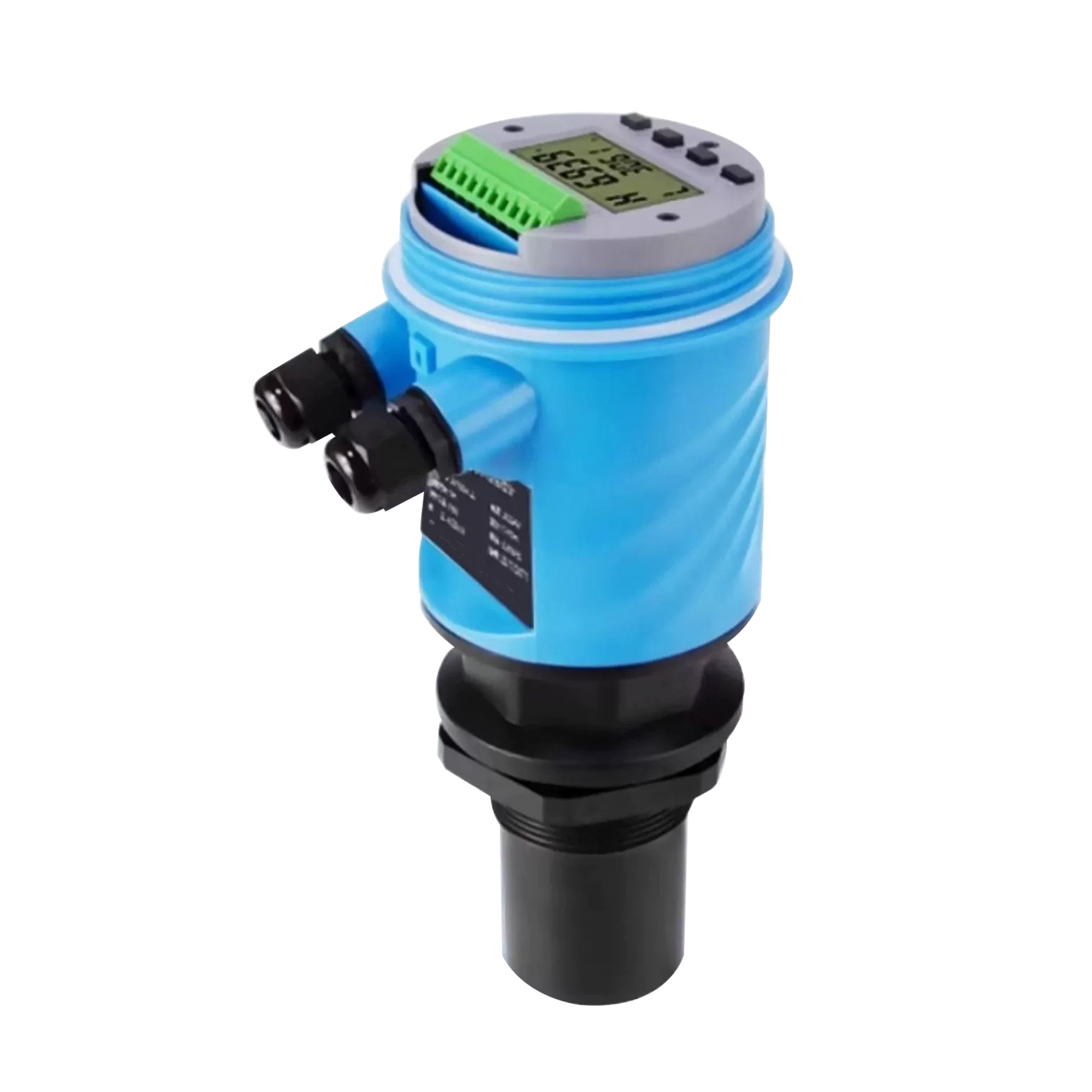
The transducer at the top launches a compression wave at roughly 1,500 metres per second in air at room temperature. The wave travels down, reflects off the liquid surface, and returns. The instrument measures the time of flight, typically a few milliseconds for a ten-metre tank, and computes range as speed multiplied by half the time.
The catch lives in that speed number. Sound moves through air at a rate set by temperature, humidity and the gas composition above the liquid. In still air at 20 °C the speed is about 1,480 m/s; for every degree the gap warms or cools, the speed shifts by roughly 0.6 m/s. Leave that uncorrected and a ten-metre measurement drifts by about six millimetres per degree — small until the tank sits outdoors through a desert day, or above a boiling evaporator where the vapour column is thirty degrees hotter than the transducer. Every competent ultrasonic meter carries a built-in temperature sensor in the transducer face for exactly this reason, and on duties with a steep temperature gradient between the sensor and the liquid we add a separate immersed resistance thermometer and feed the real gap temperature into the calculation.
Ultrasound also needs a clean, reflective surface and a clear acoustic path. The wave is mechanical, so anything that scatters, absorbs or redirects it between the transducer and the liquid steals the echo. That brings us to the four conditions that quietly sink an ultrasonic installation.
Where sound fails: the four killers
Vapour and steam. Above a hot wash tank, a boiling evaporator or a steam-blanketed buffer, the gap is full of vapour at a density and temperature the sensor cannot see with its face thermometer alone. The wave slows, the path bends, and the echo returns from somewhere that is not the liquid. We have watched an ultrasonic meter on a hot condensate tank report a level that wandered two hundred millimetres across a single shift.
Foam. A thick stable foam on top of the liquid is the worst case. The wave enters the foam, scatters among the bubbles, and the strongest echo comes back from inside the foam blanket rather than the true liquid line. Light transient foam is tolerable; a persistent blanket of proteins, surfactants or agitation foam is not.
Heavy turbulence and splash. On an agitated reactor, a violently boiling kettle or a filling jet, the surface is not a surface — it is a churning mass. The echo smears across many microseconds and the meter locks onto the crest or loses the return entirely. A stilling well or a still pipe tames this, but then you are adding mechanical hardware that radar often does not need.
Temperature gradients in the gap. Even with a face sensor, a layered gap where hot vapour sits over cold liquid fools the single-point correction. The corrected speed is wrong for part of the path.
None of these kills the technology outright. They narrow its comfortable envelope to calm, clean, low-vapour liquid surfaces in tanks where the gap temperature is honest. Inside that envelope, ultrasonic is cheap, simple, and accurate enough for most inventory and pump-control duties.
What a radar level meter actually measures
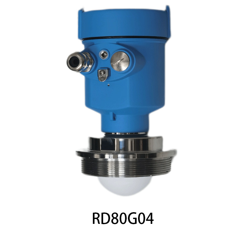
Radar launches a microwave from an antenna, reflects it off the dielectric discontinuity at the liquid surface, and times the return against the speed of light. Two transmission methods dominate. Pulsed radar measures the time of flight directly; FMCW (frequency-modulated continuous wave) sweeps the frequency and reads the beat frequency between the sent and returned signal, which gives a cleaner range and better resolution on difficult surfaces. For most process tanks today the choice that matters more than pulsed-versus-FMCW is the frequency band.
The legacy band is around 26 GHz. The newer standard, and our default for anything awkward, is 80 GHz. The reason is beam width. Antenna beam angle scales inversely with frequency for a given aperture, so an 80 GHz antenna throws a beam roughly three to four degrees wide, while a 26 GHz antenna of similar size opens to eight or ten degrees. That narrow 80 GHz beam threads past internal pipes, agitator shafts, ladders and wall brackets that a 26 GHz beam would clip and turn into false echoes. It also concentrates energy on the liquid instead of the tank wall, which is why 80 GHz reads low-dielectric liquids that 26 GHz cannot see.
The dielectric constant gate
Radar does not measure the liquid directly. It measures the boundary where the dielectric constant changes — specifically the reflection at the interface between the vapour above (εr near 1) and the liquid below (εr usually higher). The stronger the contrast in dielectric constant, the stronger the echo. Water at εr 80 gives a thunderclap of a return. Hydrocarbons sit around εr 2 to 2.5 and still reflect well at 80 GHz. The trouble starts with very low-dielectric liquids: liquefied petroleum gas around εr 1.6, some solvents, and certain light hydrocarbons. The reflection is weak, the signal-to-noise is poor, and a 26 GHz beam may simply not see the surface. In those cases we move to 80 GHz with a focused antenna, drop the meter into a stilling well to force a clean vertical path, or switch technology entirely to guided wave radar, which confines the wave to a probe and reads low-dielectric interfaces that free-space radar misses.
This is the one place where radar has a hard gate that ultrasound does not. Ultrasound cares about the surface being reflective and the path being clear; radar cares about the liquid being dielectric-different enough from the gap to return a usable echo.
Antenna fouling, condensation and the narrow neck
Radar shrugs off vapour, foam and dust in the gap because microwaves pass through them. That strength becomes a weakness when the contamination lands on the antenna itself. Condensation beading on a horn antenna, build-up caking a parabolic dish, or a coating of sticky product on the window creates a false echo at a fixed near distance that can mask the true surface return. On a saturated steam duty we specify a purged antenna housing or a drop antenna with a self-cleaning profile, and we warn the client that the antenna is now a maintenance surface, not a fit-and-forget part.
The narrow neck is the other radar-specific trap. A long thin standpipe, a dosing column, or a tank with a small top opening throws the beam down a confined space where wall reflections compete with the liquid return. This is exactly where the 80 GHz narrow beam earns its cost — it stays on axis and ignores the walls — but it still demands that we model the standpipe diameter against the beam angle before we commit the model.
Side by side: the numbers that separate them
| Criterion | Ultrasonic | Radar (80 GHz free-space) |
| Measurement principle | Sound time of flight | Microwave time of flight / FMCW |
| Typical range on liquid | 0.3 – 15 m | 0.1 – 30 m+ |
| Typical accuracy | ±2 to ±5 mm, or ±0.2–0.5% of range | ±1 to ±3 mm |
| Dead zone below sensor | 0.3 – 0.6 m | 0.05 – 0.2 m |
| Sensitivity to vapour / steam | High — primary failure mode | Negligible |
| Sensitivity to foam | High | Low (reads through) |
| Sensitivity to dust / powder in gap | High (absorbs sound) | Negligible |
| Low-dielectric liquids (LPG, solvents) | Not applicable (surface echo) | Needs 80 GHz / stilling well |
| Temperature correction | Required (gap temperature) | Not required |
| Wetted part | Transducer face only | Antenna only |
| Relative installed cost | Lower | Higher |
Read that table as a map of failure modes, not a scoreboard. Ultrasonic is not the worse instrument; it is the instrument with a narrower, clearly drawn envelope and a lower price inside it.
The liquids behind the numbers
A specification sheet stays abstract until you name the liquid it must measure. Across our installed base the two families have held level on diesel, gasoline, crude and bunker fuel. They have held level on transformer oil, silicone oil and glycerin, on molasses, syrup and wine must, on whey, milk and edible oil. They have held level on brine, pickle liquor and caustic soda, on hydrochloric, sulfuric, nitric and acetic acid, on toluene, xylene and kerosene. They have held level on asphalt, bitumen and pitch, on sludge, tailings and flocculant, on condensate, boiler feed and cooling water. They have held level on seawater, brackish water and demineralized water, and on the cold ones — liquid nitrogen, liquid oxygen, propane, butane and carbon dioxide. On the solids side they have held level on cement, fly ash, limestone, gypsum, silica, alumina, coal, coke, sand, gravel, grain, flour, sugar, salt, plastic pellet, resin bead and wood chip. On the interface side they have read oil over water, solvent over caustic, and wax over brine. Each of those liquids and solids argues for a different antenna, a different dead zone, and sometimes a different technology entirely. The meter that survives is the one specified against the medium, not against the catalogue.
When ultrasonic is the cheaper, better call
We point clients at ultrasonic first on calm, open tanks of normal liquids where the gap is clean and the temperature is honest. Typical winners:
- Water and wastewater storage, raw water clarifiers, and buffer tanks where the surface is still and the gap is ambient.
- Diesel and fuel oil storage at ambient temperature with a calm surface — a workhorse duty for the ultrasonic family.
- Brewing and beverage tanks (beer wort, wine, juice, milk) where foam is transient and the tank is open or vented.
- Open channels and weirs measured from above, where there is no pressure-rated nozzle and the liquid is moving but the level is readable.
- Bulk chemical tanks of moderate temperature with a stable surface, where the saving over radar funds three spare sensors.
On these duties an ultrasonic meter at a third of the radar price delivers the same control loop accuracy the process actually needs. Buying radar there is paying for a property the application never uses.
When radar earns its price
Radar is the default the moment the gap stops being friendly:
- Hot, boiling or steam-blanketed tanks — evaporators, condensate receivers, hot caustic and brine loops where vapour would blind ultrasound.
- Vacuum or pressurised vessels — radar has no wetted active element to fail under pressure; the antenna simply looks through the gap.
- Foamy, frothing or agitated surfaces — fermentation tanks, flashing liquids, surge drums where foam would scatter sound.
- Dusty or powder-laden headspace — although these are more often solids duties, any dusty gap that would absorb sound is a radar win.
- Low-dielectric liquids — LPG, light solvents, certain hydrocarbons, where 80 GHz or guided wave radar is the only free-space option that returns a stable echo.
- Tight geometry — narrow necks, stilling wells, internal pipes and agitators, where the 80 GHz narrow beam stays on the liquid.
- Cryogenic liquids — liquid nitrogen, liquid oxygen, LPG at temperature, where the cold, low-dielectric surface defeats both sound speed stability and weak radar reflection unless we use the right band and a probe.
If the duty checks two or more of those boxes, radar stops being the expensive option and becomes the only option that will hold the reading.
Tank geometry decides more than the medium
The liquid can be perfect and the tank can still break the measurement. We ask four geometry questions before we name a model.
First, is there a stilling well or a narrow standpipe? A well calms turbulence for ultrasonic and gives radar a clean vertical path, but it also concentrates wall reflections for radar and can trap vapour for ultrasonic. We model the well diameter against the beam angle.
Second, are there internal obstructions — heating coils, mixer shafts, ladder rungs, dip pipes? For ultrasonic these are echo sources that confuse the return; for radar, especially 26 GHz, they are false targets. The 80 GHz narrow beam is the fix when we cannot remove the obstruction.
Third, what is the nozzle length and the dead zone? Both technologies have a region directly under the sensor they cannot measure. Ultrasonic dead zones run 0.3 to 0.6 m; radar, particularly 80 GHz, can be as small as 0.05 to 0.2 m. On a short tank where the liquid can rise into the dead zone, radar reclaims usable level span that ultrasonic forfeits.
Fourth, is the surface agitated? An agitator in a reactor turns a clean echo into noise. Ultrasonic needs the well; radar with a narrow beam and good signal processing often rides through, but we still prefer a stilling well on a violently mixed vessel.
Accuracy, dead zone and the measurement you can defend
A number on a display is not the same as a number you can defend in an inventory audit. Ultrasonic meters of good make resolve to roughly ±2 to ±5 mm or about ±0.2 to ±0.5% of the measured range; radar at 80 GHz lands near ±1 to ±3 mm. For pump control, high-high alarms and day-to-day inventory, either is more than enough. For custody transfer or tank-farm reconciliation where every millimetre is money, the radar figure and its traceable calibration certificate carry the argument.
The dead zone deserves its own line because it is the property that surprises specifiers. A tank only three metres tall with an ultrasonic meter carrying a 0.5 m dead zone has lost one sixth of its measurable span before the liquid reaches a risky height. Radar halves or quarters that loss. When the tank is short and the level can run high, the dead zone — not the sticker price — decides the technology.
Outputs, Ex rating and ingress you already specify
Neither instrument lives alone. The analogue workhorse remains 4–20 mA with a relay or pulse for alarms and totalisation, and HART rides the same pair for commissioning and diagnostics. For plant integration we offer Modbus RTU, Foundation Fieldbus or Profibus PA on the bus the distributed control system already runs, because a meter that cannot talk to the control room is a meter nobody trusts.
In a tank farm, a solvent area or a gas plant the transmitter needs the Ex rating matched to the zone — flameproof Ex d or intrinsic safety Ex ia — and the ingress rating follows the location: IP67 for a weatherproof outdoor roof, IP68 for a submerged or washdown duty. A certificate on paper means nothing if the conduit entry was never sealed; the rating lives or dies at the cable gland, and we flag that on every hazardous-area drawing we return with a quote.
A selection routine we actually use
When an application engineer hands us a tank, the decision walks this path rather than guessing:
- Is the surface calm, clean and the gap near ambient, with no foam, steam or dust? If yes and the liquid is normal, start with ultrasonic — it will be the cheaper, adequate call.
- Is there vapour, steam, foam, dust, vacuum or pressure in the gap? If any one is yes, move to radar.
- Is the liquid low-dielectric (LPG, light solvent, cryogenic)? If yes, specify 80 GHz free-space with a focused antenna, or drop to guided wave radar on a probe for the toughest interfaces.
- Is the tank short, narrow-necked, or full of internal obstructions? If yes, 80 GHz narrow beam, and model the geometry against the dead zone and beam angle before release.
- Is the duty custody-transfer grade where every millimetre is reconciled? If yes, radar with a traceable calibration cert, because the audit will ask for it.
That routine is boring on purpose. Most wrong specifications come from skipping step one and buying radar for a duty ultrasonic would have handled for a third of the cost, or from skipping step two and buying ultrasonic for a steamy tank it cannot read.
Sizing the beam: dead zone and antenna angle math
Two calculations settle the geometry. The beam half-angle θ for a radar antenna of diameter D at wavelength λ is approximately θ ≈ 70 λ / D degrees for the −3 dB edge. At 80 GHz the free-space wavelength is about 3.75 mm. A 50 mm antenna gives θ ≈ 70 × 3.75 / 50 ≈ 5.25 degrees half-angle, so a ten-metre tank sees a beam roughly 1.8 metres wide at the liquid — still clearing most wall brackets. A 26 GHz antenna at the same 50 mm throws θ ≈ 70 × 11.5 / 50 ≈ 16 degrees, a 5.6-metre spot at ten metres that clips everything. That single arithmetic is why we push 80 GHz on obstructed tanks.
For ultrasonic the dead zone z sets the minimum measurable level. If the nozzle sits 0.4 m above the high alarm and z is 0.5 m, the meter cannot confirm the high alarm — a real failure mode we have caught on short tanks. We size z against the alarm setpoints on every order, not just against the tank height.
What we tune at commissioning
A meter leaves the bench generic and becomes site-specific on the day it is commissioned. On the ultrasonic side we set transducer sensitivity, blanking distance and false-echo suppression, then map the gap-temperature curve against an immersed resistance thermometer on any gradient column. On the radar side we set the echo threshold, the mapping curve and the interference blanking around agitator shafts, heating coils and dip pipes. We tune the averaging window against wave slap on an open channel, the damping against froth flutter on a fermenter, and the relay hysteresis against pump cycling on a buffer tank. We apply dielectric compensation against a known liquid on a low-epsilon duty, and we never treat those as catalogue defaults — they are the line between a meter that reads and a meter that lies.
Total cost is the second year, not the quote
The purchase price of an ultrasonic meter is a fraction of a radar meter, and on a calm tank that gap is pure saving. But total cost is the second year, not the quote. An ultrasonic meter blinded by steam on a hot tank gets pulled, re-specified and re-installed — two site visits that erase the saving and add downtime. A radar meter specified into a condensing duty without an antenna purge cakes over and needs a rope-and-harness clean every month. We size for the duty that survives the second year, because the second truck roll is the expensive one, and the third is the one clients remember when they re-specify the next plant.
Mistakes we keep pulling off tank roofs
- Buying radar for a calm water tank and paying three times for accuracy the loop never used.
- Buying ultrasonic above a boiling evaporator and wondering why the level wanders two hundred millimetres a shift.
- Forgetting the dead zone on a short tank, then discovering the high alarm sits inside the blind spot.
- Specifying 26 GHz on a tank full of internal pipes, then chasing false echoes the narrow 80 GHz beam would have ignored.
- Letting condensation cake a radar antenna on a saturated steam duty and treating the resulting drift as a calibration fault.
- Skipping the gap-temperature correction on an outdoor ultrasonic tank and watching summer noon read differently from winter dawn.
A diesel tank, a condensate receiver, a brewery fermenter, a solvent bullet, a brine evaporator, a cryogenic LPG sphere and a wastewater clarifier all look like “a level meter” until you name the gap. The selection is the product.
Why the manufacturer shows up at year three
We machine the transducer housings, wind the radar antennas, calibrate both families on our own traceable benches, and tune the signal processing for the media our clients actually pump — so the model that ships is set by one accountable shop, not a supply chain of strangers. Our ultrasonic firmware compensates the gap temperature against an immersed resistance thermometer on gradient duties, and our 80 GHz radar carries signal filtering that rides through the false echoes an obstructed tank throws at it. For OEM and ODM buyers the same instrument leaves under your label with your approvals file. When a meter drifts at a remote site in year three, you call one number and reach the people who built it, not a distributor who resells five brands and remembers none of them.
Pre-specification checklist
- Surface calm and clean, gap near ambient? → ultrasonic is likely.
- Vapour, steam, foam, dust, vacuum or pressure present? → radar.
- Liquid low-dielectric (LPG, solvent, cryogenic)? → 80 GHz or guided wave radar.
- Tank short, narrow, or obstructed? → 80 GHz narrow beam, model dead zone and beam angle.
- Custody-transfer accuracy required? → radar with traceable cert.
- Ex zone and ingress rating for the roof location confirmed?
- Dead zone checked against high and low alarm setpoints?
- Antenna purge or self-cleaning profile specified on condensing duties?
Any blank line is a question back to the client, not a guess in the quote.
When neither one is right
For a low-dielectric interface inside a stilling well, a coating liquid that fouls a free-space antenna, or a solids and powder level in a silo, neither free-space ultrasonic nor radar is the first choice. Guided wave radar — our LONN-5300 series, a probe-confined radar that reads interfaces and low-dielectric liquids that free-space radar misses — earns the call on those duties. For a clean interface in a small vessel, a magnetostrictive probe gives sub-millimetre resolution. For a simple on-off point, a float switch or a vibrating fork costs less than either continuous technology. Pick the principle first; the model follows, and the model that follows is the one that survives the second year.
Post time: Oct-19-2026


