

The Temperature Problem Is Bigger Than You Think
Here is a number that surprises most engineers: a temperature change of 10°C changes the density of water by about 0.002 g/cm³. For most organic liquids — acids, solvents, oil products — the effect is three to five times larger. A density meter with ±0.001 g/cm³ accuracy can be completely overwhelmed by a 5°C process temperature swing.
This is not a meter problem. The meter is working correctly. The physics is doing what physics does. The error comes from comparing density readings at different temperatures without converting them to a common reference temperature. If you do not compensate, you are measuring the temperature effect, not the density change you actually care about.
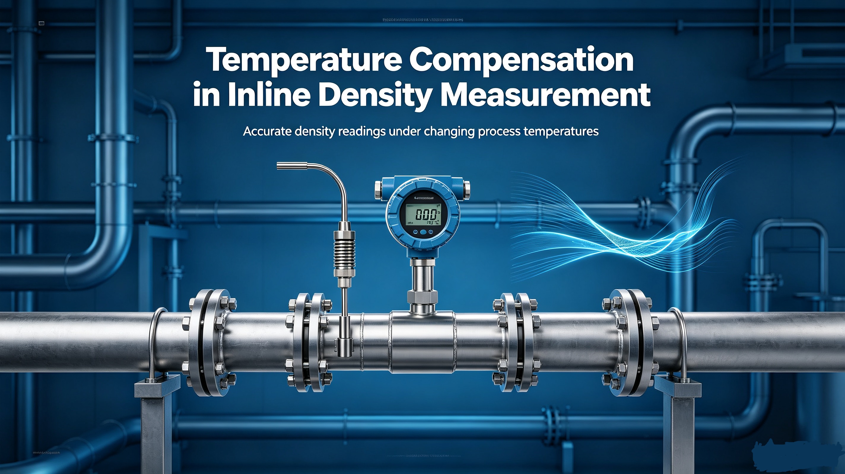
How Temperature Compensation Works
Temperature compensation converts a density reading measured at process temperature to the equivalent density at a reference temperature (usually 20°C or 15°C). The math uses the thermal expansion coefficient of the liquid.
The formula looks like this:
ρ_ref = ρ_measured / [1 + α × (T_measured − T_ref)]
Where ρ is density, α is the thermal expansion coefficient, T is temperature. The expansion coefficient α varies by liquid. Water is about 0.0002 per °C. Ethanol is 0.0011 per °C. Sulfuric acid (98%) is 0.00055 per °C. Hydrocarbon oils are around 0.0007 per °C.
The density meter measures both the process density and the process temperature simultaneously. The instrument applies the compensation formula internally and outputs the corrected density at the reference temperature.
Two Types of Compensation: Single-Fluid vs Multi-Fluid
Single-fluid compensation is the simpler case. The meter is configured for one specific liquid — for example, sulfuric acid at 50% concentration. The expansion coefficient for that specific acid concentration is programmed into the meter. Every reading is compensated using that coefficient.
Multi-fluid compensation is more flexible. The meter stores a library of expansion coefficients. When the process switches between fluids, the operator selects the correct fluid in the meter’s configuration. Some meters have auto-recognition based on the raw density reading, but this only works when the fluids have sufficiently different density signatures.
If your process runs multiple fluids through the same line — for example, a chemical plant with multiple feedstocks — make sure the density meter is configured for each fluid before relying on the compensated reading. A meter calibrated for ethanol will read wrong on methanol, even if the temperature is the same, because the expansion coefficients differ.
Thermal Expansion Coefficients for Common Liquids
|
Liquid |
Thermal Expansion Coeff (α) |
Density at 20°C |
Error / 10°C |
|
Water |
0.00020 per °C |
0.998 g/cm³ |
±0.002 g/cm³ |
|
Ethanol |
0.00110 per °C |
0.789 g/cm³ |
±0.009 g/cm³ |
|
Sulfuric acid (98%) |
0.00055 per °C |
1.835 g/cm³ |
±0.010 g/cm³ |
|
Mineral oil |
0.00070 per °C |
0.880 g/cm³ |
±0.006 g/cm³ |
|
Acetone |
0.00143 per °C |
0.790 g/cm³ |
±0.011 g/cm³ |
|
Sodium hydroxide (50%) |
0.00040 per °C |
1.530 g/cm³ |
±0.006 g/cm³ |
What Happens When Compensation Is Missing or Wrong
A density meter without temperature compensation will show density changes that are mostly temperature changes. In a batch process where the temperature rises from 25°C to 45°C during the reaction, the uncompensated density reading drops by roughly 1-2% just from thermal expansion. If the batch is supposed to reach a target density of 1.100 g/cm³, you will see it at 1.085 g/cm³ and think the reaction is incomplete when it is actually finished.
Wrong compensation — using the expansion coefficient for water when measuring acetone — makes things worse. Water has α = 0.0002/°C. Acetone has α = 0.00143/°C, which is seven times larger. A meter configured for water will undercompensate acetone by a factor of seven. The error is no longer the uncompensated reading; it is a systematically wrong reading.
Sensor Placement and Temperature Gradient Errors
Even with proper temperature compensation configured, a second error source exists: the temperature gradient between the sensor and the bulk fluid. The RTD in the density meter measures the temperature at the sensor surface. If there is a temperature difference between that point and the main body of the fluid, the compensation is applied to the wrong temperature.
This is most common in large pipes or vessels where the process temperature varies spatially. In a 500 mm pipe with hot fluid near the pipe wall and cooler fluid in the center, the sensor reading is biased by the wall temperature. The fix is to ensure the sensor is installed in a location where the flow is well-mixed and representative.
For very high accuracy applications (custody transfer, precision blending), the best practice is to install a thermowell in the process line and compare the thermowell temperature reading to the density meter’s internal temperature sensor. If they differ by more than 0.5°C, investigate the installation before relying on the compensated density.
Why Manual Compensation Is Not the Answer
Some plants try to work around the temperature problem by recording both the density reading and the temperature and applying a correction later in the data historian or a spreadsheet. This approach has two problems.
First, it only works if the operator remembers to record both values at the same time. In a busy plant, they often do not. Second, and more important: the correction is applied to the recorded data, not to the live signal going to the control system. The DCS is still controlling based on the uncompensated reading.
If you care about the density reading enough to correct it later, you should be controlling from the corrected reading in real time. That is what an inline density meter with temperature compensation does automatically.
Frequently Asked Questions About Temperature Compensation
Q: How do I find the correct thermal expansion coefficient for my process fluid?
A: For pure compounds, look up the coefficient in the CRC Handbook of Chemistry and Physics or the supplier’s technical data sheet. For mixtures, use the weighted average of the components’ coefficients. If the mixture composition varies, use the coefficient of the dominant component and accept that the compensation will be approximate.
Q: Can I compensate without the meter doing it internally?
A: You can do it externally in the DCS, but only if the meter outputs both the raw density and the temperature as separate signals. Apply the formula in the control system. This is less reliable than internal compensation because the formula is outside the instrument’s validation and audit trail.
Q: Does the meter need to be calibrated at the same temperature as the process?
A: The calibration (using reference fluids) is typically done at 20°C in the factory. The temperature compensation algorithm then handles the conversion at any process temperature within the meter’s rated range. What matters is that the temperature sensor inside the meter is accurate and that the expansion coefficient is correct for your fluid.
Q: What reference temperature should I use?
A: 20°C is the most common reference temperature in international standards and for most industrial applications. In some regions, 15°C is used (particularly in petroleum). Choose the reference temperature that matches your industry standard or your lab reference method, so that inline readings are comparable to lab results.
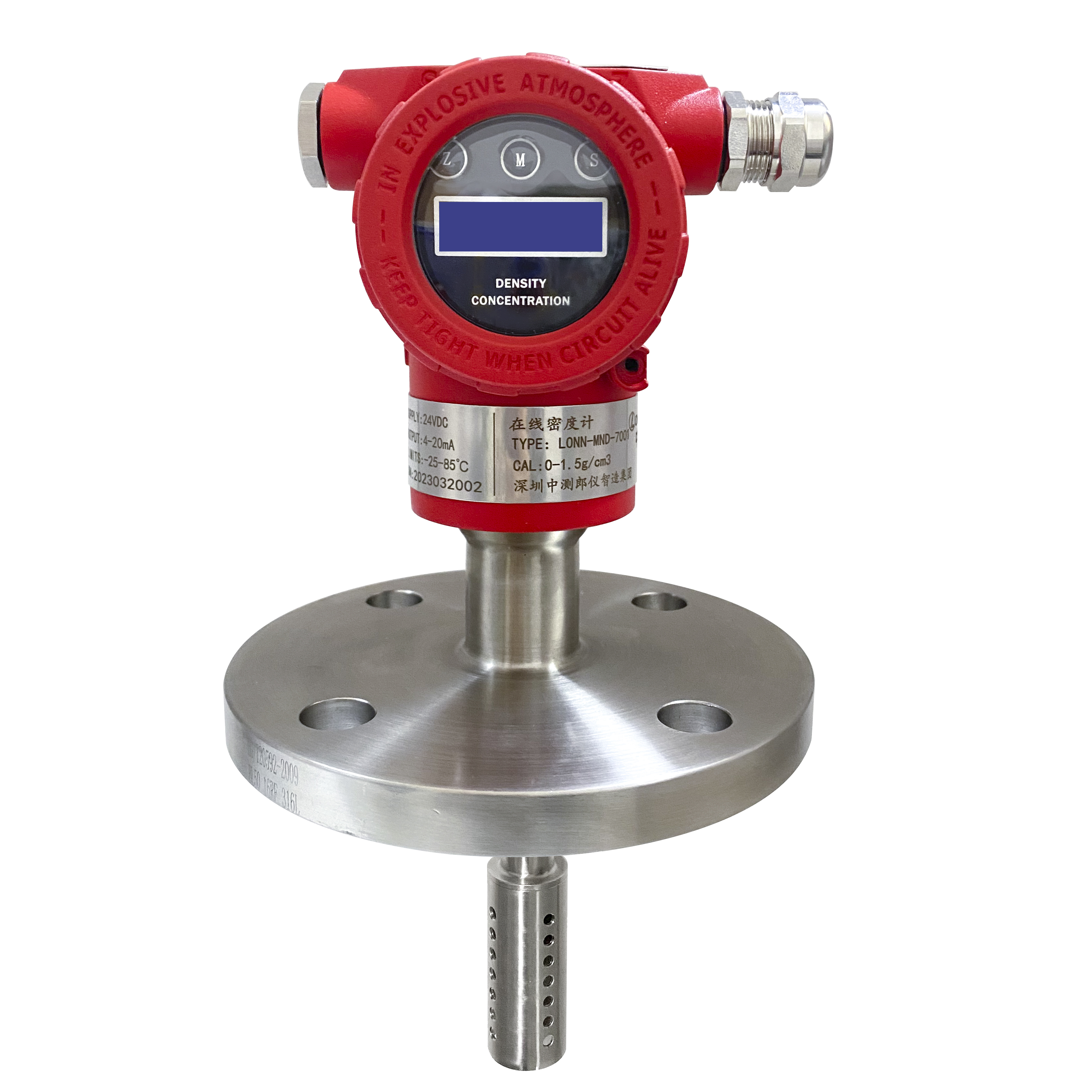
If you need to configure temperature compensation for a specific fluid in your process, the LONNMETER technical team can provide the correct expansion coefficient and walk through the configuration for the LONN-DN100 or LONN700 meter.
Post time: Jul-13-2026


