

Radar level meters look simple on the shelf until the beam clips an agitator shaft and the reading locks to the wall, or until condensation beads on the antenna and the display starts tracking a phantom surface two metres above the liquid. We build these instruments, tune their signal processing on our own traceable benches, and we still see specifiers pick the band, the antenna and the mounting in the wrong order. This guide is the internal checklist our application engineers run before a radar quote leaves the building: here is how to choose the band, the antenna and the geometry so the meter reads the liquid and not the tank.
What a radar level meter actually measures
A radar level meter launches a microwave from an antenna, reflects it off the boundary where the dielectric constant changes, and times the return against the speed of light. The instrument converts that time of flight into a distance from the antenna to the surface, then into a level against the tank height. Two transmission methods dominate the market. Pulsed radar measures the time of flight directly; FMCW (frequency-modulated continuous wave) sweeps the frequency and reads the beat frequency between the sent and returned signal. On difficult surfaces — foam, turbulence, low-dielectric liquids — FMCW gives a cleaner range and better resolution because it integrates the whole echo spectrum instead of hunting for one peak.
The physics is forgiving in one way and unforgiving in another. Microwaves pass straight through vapour, steam, dust and foam in the gap, so the headspace conditions that blind an ultrasonic meter barely register here. But the meter reads the dielectric discontinuity, not the liquid itself, and that single fact drives the entire selection.
Frequency band: 26 GHz versus 80 GHz
The band decides the beam width, and the beam width decides whether the measurement survives the tank. Antenna beam angle scales inversely with frequency for a given aperture, so an 80 GHz antenna throws a beam roughly three to four degrees wide, while a 26 GHz antenna of similar size opens to eight or ten degrees. That difference is not a spec-sheet curiosity — it is the line between a clean reading and a wall-locked one.
A 26 GHz beam on a ten-metre tank spreads into a spot five or six metres wide at the liquid. Any internal pipe, ladder, heating coil or wall bracket inside that cone becomes a false echo the meter must reject. An 80 GHz beam on the same tank stays within roughly two metres at the surface, threads past the obstructions, and concentrates its energy on the liquid instead of the steel. For obstructed tanks, narrow necks, stilling wells and agitator vessels, 80 GHz is now our default rather than an upgrade.
The trade is cost and, historically, penetration into low-dielectric liquids. The shorter 80 GHz wavelength also reflects more strongly off low-dielectric surfaces, so the band that fixes the geometry problem also helps the dielectric problem. That is why we steer most new process specifications to 80 GHz unless the tank is a simple, open, unobstructed vessel where 26 GHz still earns its lower price.
Antenna types and when each one fits
The antenna is the wetted (or near-wetted) face of the instrument, and the choice is a compromise between beam focus, contamination resistance and price.
- Horn antenna — the common free-space choice for clean liquids in a non-corrosive, non-sticky duty. Cheap, simple, easy to mount. Weak on a tank where product can coat the flare, because build-up on the horn creates a fixed near echo.
- Parabolic dish — focuses a tight beam for long range and for dusty or low-epsilon duties where every decibel of return matters. Bulky and poor in a confined nozzle, but unmatched at distance.
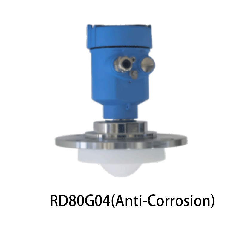
- Drop antenna (drop rod / drop lens) — hangs below the process connection so condensation and build-up form away from the active radiating face, which keeps the near echo clean on saturated-steam and condensing duties. Our preferred antenna on hot, wet headspaces.
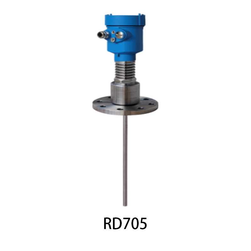
- Rod or coaxial probe (guided wave radar) — confines the wave to a probe instead of freeing it into the gap, which reads low-dielectric interfaces and liquids that free-space radar cannot see, and ignores obstructions entirely because there is no beam to clip. The probe is the antenna, and the tank geometry stops mattering.
Pick the antenna against the contamination and the geometry, not against the catalogue photo. A horn in a condensing steam duty is a service call waiting; a drop antenna there is a fit-and-forget part.
The dielectric constant gate
Radar reflects at the interface where the dielectric constant changes. The gap above the liquid sits near εr 1; the liquid below sits higher, and the stronger the contrast, the stronger the echo. Water at εr 80 returns a thunderclap. Hydrocarbons around εr 2 to 2.5 reflect well at 80 GHz. The trouble starts with very low-dielectric liquids: liquefied petroleum gas near εr 1.6, light solvents, certain hydrocarbons. The reflection is weak, the signal-to-noise is poor, and a 26 GHz beam may simply not see the surface.
For those duties we move to 80 GHz with a focused antenna, drop the meter into a stilling well to force a clean vertical path, or switch to guided wave radar on a probe, which reads interfaces that free-space radar misses. The dielectric gate is the one hard limit ultrasound does not have — ultrasound only cares that the surface reflects sound and the path is clear. Name the liquid’s dielectric constant early, because it decides the band and sometimes the technology.
The media behind that gate span an enormous range. Water and most aqueous solutions sit near εr 80 and return a signal you could read across the car park. Beer wort, wine, milk, edible oil and brine land in the high tens. Hydrocarbons — diesel, gasoline, crude, lubricating oil, asphalt, bitumen — sit around εr 2 to 2.5 and reflect well at 80 GHz. The awkward ones are the low-epsilon liquids: liquefied petroleum gas near εr 1.6, light solvents such as toluene and xylene, and cryogenic liquids such as liquid nitrogen, liquid oxygen, propane and butane, where the contrast against the gap is so small that only a focused 80 GHz beam or a guided wave probe returns a stable echo. The number on the datasheet is the difference between a reading and a guess.
Temperature and pressure at the process seal
Radar has no wetted active element to fail under pressure, which is why it reads vacuum vessels and high-pressure bullets that would wreck a sensor with a moving part. The real limit is the process seal and the flange rating, not the electronics. A standard antenna copes with moderate temperatures, but a hot duty — a bitumen tank, a molten sulphur line, a steam drum — needs a high-temperature antenna, a cooling neck that pulls the electronics away from the heat, or a waveguided drop that keeps the radiating face out of the hottest zone. The flange itself carries the pressure rating: PN, ASME or JIS classes set the wall and the gasket, and we match the class to the vessel before we match the band. Name the process temperature and pressure at the connection, because the seal, not the microwave, sets the ceiling.
Beam angle and tank geometry
The liquid can be perfect and the tank can still break the reading. We ask four geometry questions before we name a model.
First, are there internal obstructions — mixer shafts, heating coils, ladder rungs, dip pipes, thermowells? For a 26 GHz beam these are false targets; for an 80 GHz narrow beam many of them fall outside the cone and disappear. The beam width, not the liquid, often decides the band.
Second, is there a narrow neck, a long standpipe or a small top opening? A confined space throws the beam down a tube where wall reflections compete with the liquid return. This is exactly where the 80 GHz narrow beam earns its cost, but we still model the standpipe diameter against the beam angle before release.
Third, is the vessel agitated or boiling? An agitator turns a clean echo into noise. Free-space radar with good signal processing often rides through where ultrasonic needs a stilling well, but on a violently mixed reactor we still prefer a stilling well or a guided wave probe that ignores the surface chaos.
Fourth, what is the nozzle length and the dead zone beneath the antenna? Both take a slice of the tank the meter cannot measure, and on a short tank that slice can swallow the high alarm.
Antenna fouling, condensation and build-up
Radar shrugs off what is in the gap, but it is helpless against contamination on the antenna itself. Condensation beading on a horn, build-up caking a dish, or a sticky product filming a window creates a false echo at a fixed near distance that can mask the true surface. On a saturated steam duty we specify a drop antenna with a self-cleaning profile or a purged housing, and we warn the client that the antenna is now a maintenance surface, not a fit-and-forget part. A coated antenna that drifts is a calibration fault only until you wipe it — then it was never a calibration fault at all.
Range, signal budget and the limit of distance
Radar reaches further than almost any other level technology, but the reach is a signal budget, not a number on the box. The wave leaves the antenna with a fixed power, loses some to the antenna and the gap, reflects off the surface, and returns weaker by the square of the distance. A two-wire, loop-powered meter draws its power from the 4–20 mA loop, which caps the transmit energy and quietly limits the range; a four-wire meter with a separate supply transmits harder and reaches further. Atmospheric attenuation is negligible for microwave in air, so the gap composition barely matters — unlike ultrasound, which loses energy to vapour and dust. The practical ceiling on a clean high-dielectric liquid runs past thirty metres for a four-wire unit; on a low-epsilon liquid the weak reflection eats the margin, and we derate the range or step to guided wave radar, which loses almost nothing along the probe. Read the stated range against your liquid’s dielectric constant, not against the brochure’s water assumption.
Dead zone and the span you can defend
Every radar meter has a region directly under the antenna it cannot measure, but the size varies sharply with band and antenna. A 26 GHz horn may carry a dead zone of 0.3 to 0.6 m; an 80 GHz antenna with a small dead zone can be as tight as 0.05 to 0.2 m. On a tank only three metres tall, a 0.5 m dead zone forfeits one sixth of the measurable span before the liquid even reaches a risky height. Radar reclaims usable level that ultrasonic forfeits, and on short tanks the dead zone — not the sticker — decides the technology.
Accuracy and the number you can defend
A good 80 GHz meter resolves to roughly ±1 to ±3 mm; a 26 GHz meter lands nearer ±3 to ±10 mm depending on surface and antenna. For pump control, high-high alarms and day-to-day inventory, either is more than enough. For custody transfer or tank-farm reconciliation where every millimetre is money, the 80 GHz figure and its traceable calibration certificate carry the argument, because the audit will ask for the certificate, not the display.
Outputs, Ex rating and ingress you already specify
The analogue workhorse remains 4–20 mA with a relay or pulse for alarms and totalisation, and HART rides the same pair for commissioning and diagnostics. For plant integration we offer Modbus RTU, Foundation Fieldbus or Profibus PA on the bus the distributed control system already runs, because a meter that cannot talk to the control room is a meter nobody trusts. In a tank farm, a solvent area or a gas plant the transmitter needs the Ex rating matched to the zone — flameproof Ex d or intrinsic safety Ex ia — and the ingress rating follows the location: IP67 for a weatherproof outdoor roof, IP68 for a submerged or washdown duty. A certificate on paper means nothing if the conduit entry was never sealed; the rating lives or dies at the cable gland, and we flag that on every hazardous-area drawing we return with a quote.
Sizing the beam: the angle math
The beam half-angle θ for an antenna of diameter D at wavelength λ is approximately θ ≈ 70 λ / D degrees at the −3 dB edge. At 80 GHz the free-space wavelength is about 3.75 mm, so a 50 mm antenna gives θ ≈ 70 × 3.75 / 50 ≈ 5.25 degrees half-angle — a beam about 1.8 m wide at ten metres, still clearing most wall brackets. A 26 GHz antenna at the same 50 mm throws θ ≈ 70 × 11.5 / 50 ≈ 16 degrees, a 5.6 m spot at ten metres that clips everything in the cone. That single line of arithmetic is why we push 80 GHz on obstructed tanks and model the beam against every internal obstruction before we release the model.
Free-space radar versus guided wave radar
When the free-space beam cannot win — a low-dielectric interface, a coating liquid that fouls any antenna, or a duty where obstructions make a free beam unusable — guided wave radar earns the call. Our LONN-5300 series confines the wave to a rod or cable probe, reads oil over water, solvent over caustic and wax over brine, and ignores tank geometry because there is no beam to clip. Free-space radar wins on simple, open, non-coating liquids where you want no probe in the tank; guided wave wins on the hard interfaces and the dirty, low-epsilon duties. The two are not competitors so much as neighbours on the same selection map, and naming which one comes first saves the second truck roll.
What we tune at commissioning
A radar meter leaves the bench generic and becomes site-specific on commissioning day. We set the echo threshold, the mapping curve and the interference blanking around agitator shafts, heating coils and dip pipes. We tune the averaging window against wave slap on an open channel, the damping against froth flutter on a fermenter, and the relay hysteresis against pump cycling on a buffer tank. We apply dielectric compensation against a known liquid on a low-epsilon duty, and we never treat those as catalogue defaults — they are the difference between a meter that reads and a meter that lies.
Total cost is the second year, not the quote
The purchase price of a radar meter is real, and on a calm open tank it can feel like paying for properties the duty never uses. But total cost is the second year, not the quote. A 26 GHz meter specified into an obstructed tank gets pulled and re-specified after it locks onto a pipe; an antenna that cakes on a condensing duty needs a rope-and-harness clean every month. We size for the duty that survives the second year, because the second truck roll is the expensive one, and the third is the one clients remember when they re-specify the next plant.
Mistakes we keep finding on site
- Buying radar for a calm water tank and paying three times for accuracy the loop never used — ultrasonic would have done it for a third.
- Specifying 26 GHz on a tank full of internal pipes, then chasing false echoes the narrow 80 GHz beam would have ignored.
- Letting condensation cake a horn antenna on a saturated steam duty and treating the resulting drift as a calibration fault.
- Forgetting the dead zone on a short tank, then discovering the high alarm sits inside the blind spot.
- Skipping the dielectric check on a low-epsilon liquid, then wondering why the 26 GHz beam never saw the surface.
- Leaving the cable gland unsealed on a hazardous-area rating, so the Ex certificate dies at the conduit entry.
A diesel tank, a condensate receiver, a brewery fermenter, a solvent bullet, a brine evaporator, a cryogenic LPG sphere, a liquid nitrogen dewar and a wastewater clarifier all look like “a radar level meter” until you name the band, the antenna and the gap. The selection is the product.
Why the maker shows up at year three
We machine the housings, wind and tune the antennas, calibrate both free-space and guided wave families on our own traceable benches, and filter the signal processing for the media our clients actually pump — so the model that ships is set by one accountable shop, not a supply chain of strangers. Our 80 GHz firmware carries interference blanking that rides through the false echoes an obstructed tank throws at it, and our drop-antenna design keeps condensation off the active face on the hot, wet duties that foul a horn. For OEM and ODM buyers the same instrument leaves under your label with your approvals file. When a meter drifts at a remote site in year three, you call one number and reach the people who built it, not a distributor who resells five brands and remembers none of them.
Pre-specification checklist
- Liquid dielectric constant known? Low-epsilon (LPG, solvent, cryogenic) → 80 GHz or guided wave radar.
- Tank obstructed, narrow-necked, or with an agitator? → 80 GHz narrow beam, model beam angle against obstructions.
- Surface calm and clean, open vessel? → 26 GHz may earn the lower price.
- Contamination on the antenna expected (steam, sticky product)? → drop antenna or purge; plan maintenance.
- Dead zone checked against high and low alarm setpoints on a short tank?
- Custody-transfer accuracy required? → 80 GHz with traceable calibration cert.
- Ex zone and ingress rating for the roof location confirmed, gland sealed?
- Output and bus (4–20 mA, HART, Modbus, Fieldbus, Profibus) matched to the DCS?
Any blank line is a question back to the client, not a guess in the quote.
When this is not the radar you want
For a calm, clean, low-vapour liquid surface in an open tank at ambient temperature, an ultrasonic meter at a third of the price delivers the same control-loop accuracy the process needs — buying radar there spends on a property the application never uses. For a low-dielectric interface, a coating liquid or an obstructed vessel where no free beam can win, guided wave radar on a probe is the call, not free-space. Pick the principle first; the model follows, and the model that follows is the one that survives the second year.
Post time: Oct-21-2026


