

A line on a bill of materials that reads “0 to 10 bar, 4 to 20 mA, 316L” is not a specification. It is three specifications wearing one coat. Gauge, absolute and differential instruments will all satisfy those words, all arrive in apparently identical housings, all wire into the same analogue input, and all put a plausible number on the HMI. Two of them will be wrong for the process, and the wrongness will not announce itself as a fault. It shows up as a vacuum reading that drifts with the weather, a closed-tank level that rises when nobody has filled the vessel, or a flow signal that reads backwards after a shutdown. This pressure transmitter selection guide starts from that failure, because the reference type is the first decision in any pressure transmitter range enquiry and the one most often left off the datasheet.
We build all three on the same production line, so the question is not which one we would rather sell. It is which physical quantity the loop is actually trying to measure. Once that is written down, the rest of the specification, from range to manifold, follows with far less argument.
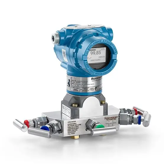
Three reference points, one housing
Pressure is always a difference. The only question is what sits on the other side of the sensing diaphragm. A gauge instrument vents that side to local atmosphere, so its zero is the air around the plant. An absolute pressure transmitter seals a hard vacuum behind the diaphragm, so its zero is a true physical zero. A differential pressure transmitter brings a second process pressure to the back of the cell and reports the gap between the two ports.
The arithmetic is uncomplicated and worth keeping visible:
| Relation | Expression | Consequence |
| Absolute from gauge | p_abs = p_g + p_atm | A gauge reading needs local barometric pressure to become absolute |
| Gauge from absolute | p_g = p_abs – p_atm | An absolute cell open to air reads about 1013 mbar, not zero |
| Differential | Δp = p_high – p_low | Static line pressure cancels only if the cell is rated for it |
| Hydrostatic head | Δp = ρ g h | Density and geometry turn a pressure into a level |
| Orifice flow | Q ∝ √Δp | Flow needs square-root extraction somewhere in the loop |
ISO 2533 gives the standard atmosphere used for altitude corrections, and it explains why a vented gauge device behaves differently on a coastal site and on a plateau. At roughly 1500 m elevation the ambient pressure is near 840 mbar instead of 1013 mbar, a difference of about 170 mbar. On a 10 bar process line that is noise. On a 0 to 250 mbar furnace draft measurement it is most of the span, and on a vacuum specification written as “-0.8 bar g” versus “200 mbar abs” it is the difference between two entirely different instruments. This pressure transmitter selection guide treats the unit suffix as part of the specification, not as a formatting preference.
Barometric pressure also moves with the weather. A strong depression can shift ambient pressure by 30 to 50 mbar over a day or two. A low-range gauge unit that is physically vented tracks that shift automatically because both sides of its diaphragm see the same air, which is exactly why gauge reference is the right answer for most open systems. An absolute cell ignores it entirely. A specification that needs a true zero must not be built by subtracting a barometer reading from a gauge transmitter in software, because that adds a second instrument, a second calibration and a slowly changing offset to every value in the historian.
When atmosphere is the wrong reference
Vacuum and vapour-pressure work belong to the sealed cell. A freeze dryer running a chamber at 0.1 kPa abs is controlling a physical state, not a pressure above the room. Distillation columns are similar, because relative volatility and boiling point are functions of absolute pressure, and a recipe developed at one barometric condition will not reproduce if the control variable silently includes the weather. Gas-law calculations, density compensation, altitude simulation and leak-rate tests sit in the same category.
There is a commercial wrinkle here. Absolute ranges are often specified in mbar abs or kPa abs down to a few mbar full scale, and at those spans the sensor is working near the limits of what a metal diaphragm can resolve with good long-term stability. Buyers who ask for “0 to 1 bar abs, 0.1% accuracy” sometimes need a vacuum gauge technology rather than a general-purpose process transmitter, and a supplier who quotes without asking will win the order and lose the commissioning. We ask what the true minimum pressure is, whether the process ever sees full atmosphere or a cleaning steam pulse, and whether a gauge unit with a wide negative range would survive the upset. That conversation is the practical core of a pressure transmitter selection guide, and it cannot be replaced by a comparison table.
The LONN-2088 gauge and absolute model covers both references on one platform, which is useful for plants that standardise spares across a site. It does not make the two references interchangeable. Swapping a spare from one service to the other without re-ranging the loop is a classic source of a reading that looks stable and is offset by exactly one atmosphere.
A vent hole is a maintenance item
Gauge reference vents to the air around the plant, which makes it the least expensive and most common choice for pump discharge, compressed air headers, hydraulic skids, open tanks and utility services. Its weakness is mechanical rather than electronic. The reference side has to breathe, and whatever lets air in can also let water, dust, cleaning fluid or paint in.
We have opened transmitters returned from a washdown area where the vent had been sealed by a maintenance painter, and others where a clogged sintered plug had trapped a pressure that changed with the sun on the enclosure. Both read convincingly. Neither was measuring process pressure any more. IEC 60529 gives the ingress ratings people specify, but an IP67 claim and a functioning atmospheric reference are not the same thing, and a hydrophobic membrane that keeps a pressure washer out while equalising slowly is a design choice, not a checkbox. On a low-range instrument, even a few millibar of trapped reference pressure is a large fraction of span.
Mounting orientation matters for the same reason. A vent pointed upward in an outdoor installation collects condensate. A vent pointed into a cable gland collects cable-gland sealant. Options such as a remote vent line to a dry cabinet, or a sealed-gauge reference where the application allows it, exist precisely for these cases. A sealed-gauge cell references a fixed trapped pressure instead of living atmosphere and is a legitimate answer for high-altitude installations, but it is neither absolute nor ordinary gauge and must be labelled as such in the loop drawings. The industrial pressure transmitter pages we supply show which vent and enclosure options are available on each platform, and the pressure measuring transducers range covers the OEM variants where the reference is fixed at build time.
Two ports, one cell, and a static pressure nobody specified
Differential measurement is where most specification errors become expensive, because the number being measured is often tiny compared with the pressure both ports are sitting under. A filter on a 40 bar line may develop 300 mbar of drop. A DP transmitter on that service sees 40 bar of common-mode static pressure on both sides and must resolve a 300 mbar difference on top of it. The static pressure rating and the differential span are separate line items, and the first one is regularly omitted.
Static pressure effect is a real datasheet term, not a theoretical worry. It describes how much the indicated differential shifts when line pressure rises from ambient to operating, and on a low differential span that shift can exceed the measurement itself. Zeroing a DP cell with both ports at atmosphere is standard practice on the bench, but if the installed loop is equalised at full line pressure instead, the correction belongs in the commissioning record. High-static differential designs exist for this reason, with isolating diaphragms and fill-fluid arrangements that keep the sensing element balanced.
One-sided overpressure is the other hazard. Opening the wrong valve on a three-valve or five-valve manifold, or starting a pump with the equalising valve closed, can put full line pressure on the low side alone. A general-purpose differential cell may be rated for only a few times its span in that direction. The manifold, the equalising procedure and the overload rating are one decision, and they are written into the installation method statement, not discovered by the first shift that trips a pump. Our differential pressure transmitter listings separate the differential span, the static rating and the one-sided overload limit for that reason.
Range selection is an error budget, not a safety margin
Buyers who have been burned by a pressure spike tend to oversize the range. It feels conservative. On a transmitter specified as a percentage of calibrated span it is the opposite, because the error band is a fixed width in pressure units no matter where in the span the process sits.
| Selected range | Stated accuracy | Absolute error band | Error on a 2 bar reading |
| 0 to 10 bar | ±0.5% of span | ±0.05 bar | ±2.5% of reading |
| 0 to 40 bar | ±0.5% of span | ±0.20 bar | ±10% of reading |
| 0 to 100 bar | ±0.5% of span | ±0.50 bar | ±25% of reading |
The three instruments carry the same headline accuracy. Their usefulness at the operating point differs by an order of magnitude. IEC 61298-2 and IEC 60770-1 define how performance claims are evaluated, and reading those methods makes clear why the normal operating point should sit in the upper part of the calibrated span while the upset pressure is handled by a separate overload rating, a snubber or a diaphragm seal. Turndown is a convenience for standardising spares, not a licence to run a 100 bar sensor at 2 bar indefinitely.
A datasheet normally lists several distinct pressure limits. The calibrated span maps pressure to output. The overload or overrange pressure is a short-duration survival figure. The proof pressure and burst pressure describe mechanical integrity. Static pressure applies to differential devices only. None of these is interchangeable, and a pressure transmitter selection guide that collapses them into “max pressure” has already lost the information the buyer needs. Pulsating services from reciprocating pumps and hydraulic systems add a fatigue dimension that a static overload number does not cover, which is where a snubber, a restrictor or a filled impulse line earns its place.
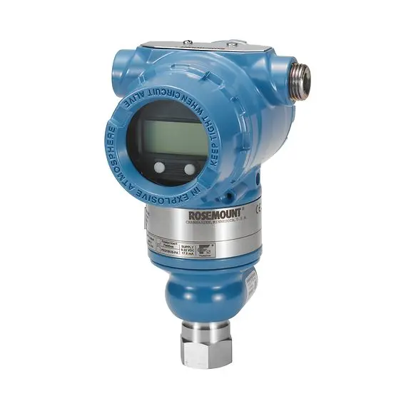
The selection arithmetic for three real services
Numbers expose the looseness of adjectives, so here are three enquiries we see repeatedly, with the reasoning that changes between them.
A vacuum drying oven wants chamber control between 5 and 200 mbar abs with a steam-in-place cycle that briefly reaches 130 °C and full atmospheric pressure. The reference is absolute. The range is set by the low end, because the control resolution near 5 mbar is what the process cares about, and the excursion to atmosphere is handled by an overload rating rather than by stretching the span. A remote seal or a cooled adapter keeps the electronics away from the cycle temperature. The output scaling in the PLC must be written in mbar abs, and the calibration needs a vacuum reference rather than a vented zero.
A booster pump on an open treated-water tank is a gauge job. Normal discharge is 4.5 bar g with a deadhead near 7 bar g and a water-hammer spike beyond that. A 0 to 10 bar g span places the operating point near mid-scale with headroom for the deadhead, the spike is covered by overload and a snubber, and a vented reference is fine because the tank is open to atmosphere. Nothing in this loop needs a barometer, a second port or a vacuum reference. Adding any of them raises cost and adds failure modes.
A closed condensate vessel at 12 bar needs level from hydrostatic head. A single gauge transmitter at the bottom reads tank pressure plus head and cannot separate the two. A differential pressure transmitter with the low port connected to the vapour space cancels the 12 bar and reports ρ g h, but the specific gravity changes with temperature, so the level calculation needs a density assumption that is documented rather than implicit. This is the same geometry as the filtration service in our earlier application note, and it is why the pressure transmitters process solutions documentation asks for the vessel drawing before quoting the span.
Where DP quietly becomes level, flow or filter condition
A differential transmitter rarely measures a pressure for its own sake. It is a transducer for some other variable, and the conversion introduces its own error budget.
For flow across an orifice plate, ISO 5167-2 fixes the geometry and the discharge coefficient assumptions. Flow is proportional to the square root of the differential, so a 1% error in Δp becomes roughly 0.5% in flow, but the same square-root relationship destroys resolution at low flow. At 10% of maximum flow the differential is 1% of maximum Δp, and that is why turndown claims on DP flow need to be read against the transmitter’s low-end accuracy, not its headline figure. Whether the square-root extraction happens in the transmitter or in the DCS changes the scaling, the alarm behaviour below the cut-off and what a technician sees during a loop check.
For level in a pressurised vessel, the density term is the dominant uncertainty. For filter monitoring, the interesting event is a slow climb from maybe 20 mbar to 250 mbar, which argues for a low differential span and a high static rating simultaneously. Clean-room and nitrogen-blanketing duties go lower still, and our note on slight positive pressure control for nitrogen blanketing covers what happens when a few pascals of pressure decide whether a tank breathes in moist air. In each case the instrument is a pressure device and the controlled variable is something else, so the specification has to state both. That is why this pressure transmitter selection guide asks for the derived variable, the primary-element geometry and the density assumption on the enquiry form, not merely a differential span.
Output, protocol and what the PLC actually scales
The reference type decides the physics. The output decides whether the number arrives in the control system in the right units. A two-wire 4 to 20 mA loop remains the default because it is easy to document and every maintenance crew can trouble-shoot it with a multimeter. NAMUR NE 43 defines the out-of-range signal levels used to distinguish a valid overrange from a sensor failure, and that convention only helps if the receiving card is configured to interpret it.
HART adds ranging, diagnostics and device identification over the same pair of wires. It also introduces a second place where LRV and URV can be set, which is a gift and a trap. We have traced more than one “failed transmitter” to a HART re-range that changed the 4 mA and 20 mA points while the PLC scaling stayed at the original values. The instrument was correct, the historian was not. A pressure transmitter selection guide has to mention the scaling because it is where a correct instrument produces a wrong process value, and no amount of accuracy at the sensor fixes it.
Units are part of the same problem. bar g, bar a, kPa Δp, mbar abs, mmH2O and psi are not decoration. A loop drawing that says “0 to 10 bar” without a suffix forces the panel builder to guess, and the guess gets baked into the HMI, the alarm setpoints and the batch record. Our 4-20 mA pressure transmitter documentation spells out the mapping between range, output and engineering units, and the pressure sensor vs transducer vs transmitter explainer is worth reading before a BOM mixes those three device names.
Wetted parts, seals and the process connection
Reference type and range are invisible on a photograph. The process connection is not, and it is where installation conflicts surface. NPT and G threads, DIN and ANSI flanges, and hygienic clamp fittings are not interchangeable, and a transmitter ordered with the wrong one becomes a machining job on site.
Material selection follows the fluid. 316L handles water, air, light oils and many utilities. Chloride-bearing streams, acids and sour hydrocarbons push toward Hastelloy C-276, Monel, tantalum or a coated diaphragm, with EN 10204 3.1 certificates requested when the material traceability is contractual. A remote seal with capillary moves the sensing cell away from a hot or crystallising process, but the fill fluid, the capillary length and the ambient temperature swing all feed into zero stability and response time. A long capillary in direct sun can produce a slow drift that looks exactly like a process change. This is a mechanical subsystem with its own thermal error, not a mounting accessory.
Hazardous areas add another layer. IEC 60079 and ATEX 2014/34/EU govern the protection method, and our how pressure transmitters improve safety in hazardous environments note covers the enclosure, barrier and earning decisions. The reference type does not change the certification, but it changes which ports exist, which means the gland and manifold arrangement has to be re-checked when a gauge unit is swapped for a differential one. No pressure transmitter selection guide is complete without that audit, because a flameproof housing with the wrong gland count or manifold layout still fails the loop check.
Temperature, drift and the zero you did not re-check
Accuracy at 20 °C on a bench is a procurement number. The installed instrument lives through ambient swings, process heat, steam cleaning and winter shutdowns, and every one of those moves the zero. Datasheets split the effect into a zero coefficient and a span coefficient, usually expressed per degree or over a stated temperature band. On a low-range absolute or differential device, the thermal zero shift can be a meaningful share of the span, so the budget has to be computed at the worst ambient, not at the calibration temperature.
Impulse lines carry their own errors. Liquid legs in a gas service create a head offset that depends on how much condensate has collected. Gas pockets in a liquid service make the reading sluggish or hysteretic. Unequal leg lengths on a DP installation produce apparent differential that changes with ambient temperature, and a frozen leg in an unheated line stops reporting altogether. Short, equal, sloped and heat-traced where necessary is the whole doctrine. We re-zero at operating temperature after the plant has reached steady state, and we log the zero before and after trimming, because a bias introduced during a cold start stays with the loop for the rest of the run.
Calibration turns the reference type from a word on a drawing into a physical procedure. A gauge unit is zeroed with its port open to atmosphere and checked against a piston gauge or a pressure comparator at several points up the span. An absolute unit needs a vacuum reference and a primary standard capable of resolving the low end, while a differential unit is zeroed with both ports equal before any static pressure is applied. As-found and as-left readings, hysteresis on the return leg, repeatability at one point and linearity across the span belong in the certificate, together with the recalibration interval the site has chosen. Traceability to ISO/IEC 17025 tells an auditor how those numbers were produced, but it says nothing about whether the loop was ranged in bar g or bar a. That distinction lives in the configuration, and the two documents have to agree.
Failures we are asked to diagnose
Most of the calls we take are not instrument faults. They are reference, range or scaling decisions that were never written down.
| Symptom on site | Usual cause | What to check first |
| Vacuum value drifts with weather | Gauge cell used where absolute was needed | Unit suffix on the datasheet and loop drawing |
| Closed-tank level rises without filling | Bottom gauge tap, no vapour-space compensation | Low-port connection and density assumption |
| Low-range reading offset by about one bar | Vent blocked, or absolute spare fitted to a gauge loop | Vent plug, spare part number, LRV/URV |
| DP flow reads backwards after a restart | High and low ports reversed at the manifold | Impulse line tagging and equalising procedure |
| Filter DP creeps upward in sunshine | Capillary or impulse-leg thermal effect | Fill fluid, leg lengths, trace heating |
| HMI value disagrees with a local gauge | PLC scaling or HART re-range mismatch | 4 mA and 20 mA engineering values |
| Alarm never trips on a healthy loop | Oversized span hiding the setpoint | Accuracy as a share of reading, not of span |
| Reading collapses at high line pressure | Static pressure effect beyond the cell rating | Static rating separate from differential span |
Each row is a decision that a pressure transmitter selection guide should have forced before the purchase order. None of them appears as a diagnostic alarm on the device, because the transmitter is doing exactly what it was built to do.
A specification sheet that buys the right instrument
This is the checklist we issue with every pressure transmitter selection guide, and the sequence is deliberate. Reference type first, then range in explicit units, then static and overload limits, then everything downstream.
State gauge, absolute, differential or sealed gauge as a named value. Give the minimum, normal and maximum operating pressure plus start-up, shutdown, cleaning and deadhead cases, each with a unit suffix. For differential service, give the maximum static line pressure and the one-sided overload separately. Name the medium, its temperature range, whether it can crystallise, polymerise or carry solids, and the required wetted materials. Specify the process connection and its standard, the mounting orientation and any remote seal or capillary. Give the output as 4 to 20 mA with or without HART, the LRV and URV in engineering units, and where square-root extraction happens. Add the ambient temperature range, ingress rating, hazardous-area classification, and any SIL or material-certificate requirements. Finally, state the calibration and documentation expected at handover.
That list is what turns a pressure transmitter price enquiry into a comparable quotation. Two suppliers quoting different reference types against a vague BOM are not offering the same instrument, and the cheaper number is often the one that omits a manifold, a seal or a static rating. Our piece on how to choose the right oil pressure transmitter works through the same discipline for hydrocarbon duty, and the inline pressure measurement in gasoline refinery distillation note shows what a complete line list looks like on a real column. For plants that also need a manufacturer-level conversation about volume builds, the china pressure transmitter page covers the OEM side of the same platform.
What LONNMETER builds on each reference
LONNMETER GROUP develops, manufactures and sells these instruments as one organisation, so the reference decision is an engineering conversation rather than a sales handoff. The LONN-3051 coplanar platform serves differential and gauge configurations where a manifold and a compact process interface matter. The in-line mounting platform covers direct-mount gauge and absolute duties. The LONN-2088 gauge and absolute transmitter gives sites a common spare across two reference types. Calibration is traced through deadweight testers and pressure comparators with laboratory accreditation to ISO/IEC 17025, and each shipment carries its own certificate rather than a generic accuracy claim.
What we will not do is quote an accuracy, a static pressure rating, a protection marking or a SIL claim for a configuration we have not built. The exact figures for any model live on its datasheet and the certificate shipped with it, and the numbers in this guide describe the selection method, not a promise for an unstated application. A pressure transmitter selection guide is useful precisely because it slows the ordering step down long enough to write the reference down.
Tell us the reference, the range with units, the static and upset pressures, the medium, the connection and the loop function. The contact page is where that starts, and it moves faster when the line list arrives with the first message.
Post time: Nov-13-2026


