

Epoxy resins are essential in an extensive array of industrial scenarios, ranging from composite material manufacturing to the development of specialized adhesives. Among the fundamental properties that define these resins, viscosity emerges as a core characteristic—one that exerts a profound influence on their manufacturing processes, application methods, and the ultimate performance of the end products.
Epoxy Resin Manufacturing Process
1.1 Core Manufacturing Steps
The manufacturing of epoxy resins is a multi-stage chemical synthesis process. The core of this process is the precise control of reaction conditions to convert raw materials into liquid resins with specific physicochemical properties. A typical batch production process begins with the procurement and mixing of raw materials, primarily bisphenol A (BPA), epichlorohydrin (ECH), sodium hydroxide (NaOH), and solvents like isopropanol (IPA) and deionized water. These ingredients are mixed in a pre-mixer tank at a precise ratio before being transferred to a reactor for the polymerization reaction.
The synthesis process is generally carried out in two steps to ensure high conversion and product consistency. In the first reactor, sodium hydroxide is added as a catalyst, and the reaction proceeds at approximately 58 ℃ to achieve about 80% conversion. The product is then transferred to a second reactor, where the remaining sodium hydroxide is added to complete the conversion, yielding the final liquid epoxy resin. Following the polymerization, a series of complex post-processing steps are carried out. This includes diluting the sodium chloride (NaCl) byproduct with deionized water to form a brine layer, which is then separated from the resin-rich organic phase using conductivity or turbidity probes. The purified resin layer is then further processed via thin-film evaporators or distillation columns to recover excess epichlorohydrin, resulting in the final, pure liquid epoxy resin product.

1.2 Comparison of Batch vs. Continuous Production Processes
In epoxy resin manufacturing, both batch and continuous production models have distinct advantages and disadvantages, leading to fundamental differences in their viscosity control needs. Batch processing involves feeding raw materials into a reactor in discrete batches, where they undergo a sequence of chemical reactions and thermal exchanges. This method is often used for small-scale production, custom formulations, or products with high diversity, offering flexibility to produce specialized resins with specific properties. However, batch production is associated with longer production cycles and inconsistent product quality due to manual handling, raw material variability, and process fluctuations. This is precisely why production and process engineers frequently identify "poor batch-to-batch consistency" as a core challenge.
Conversely, continuous production operates with a steady flow of materials and products through a series of interconnected reactors, pumps, and heat exchangers. This model is preferred for large-scale manufacturing and high-demand, standardized products, offering superior production efficiency and greater product consistency due to automated control systems that minimize process variations. Nevertheless, continuous processes require a higher initial investment and more sophisticated control systems to maintain stability.
The fundamental differences between these two modes directly impact the value of in-line viscosity monitoring. For batch production, real-time viscosity data is essential to compensate for inconsistencies caused by manual intervention and process variations, enabling operators to make data-driven adjustments rather than relying on experience alone. In-line viscosity monitoring fundamentally transforms a reactive, post-production quality check into a proactive, real-time optimization process.
1.3 The Critical Role of Viscosity
Viscosity is defined as a fluid's resistance to flow, or its measure of internal friction. For liquid epoxy resins, viscosity is not an isolated physical parameter but a core indicator directly linked to the progress of the polymerization reaction, molecular weight, degree of cross-linking, and final product performance.
During the synthesis reaction, changes in viscosity of epoxy resin directly reflect the growth of molecular chains and the cross-linking process. Initially, as temperature rises, the viscosity of the epoxy resin decreases due to increased molecular kinetic energy. However, as the polymerization reaction begins and a three-dimensional cross-linked network forms, viscosity increases dramatically until the material fully cures. By continuously monitoring viscosity, engineers can effectively track the reaction's progress and accurately determine the reaction endpoint. This not only prevents the material from solidifying inside the reactor, which would require costly and time-consuming manual removal, but also ensures the final product meets its target molecular weight and performance specifications.
Furthermore, viscosity has a direct impact on downstream applications and processability. For example, in coating, adhesive, and potting applications, viscosity dictates the resin's rheological behavior, spreadability, and its ability to release trapped air bubbles. Low-viscosity resins facilitate bubble removal and can fill minute gaps, making them suitable for deep-pour applications. High-viscosity resins, in contrast, have non-drip or non-sag properties, making them ideal for vertical surfaces or sealing applications.
Therefore, viscosity measurement provides fundamental insight into the entire epoxy resin manufacturing chain. By implementing real-time, precise viscosity monitoring, the entire production process can be diagnosed and optimized in real-time.
2. Viscosity Monitoring Technologies: A Comparative Analysis
2.1 Operating Principles of In-line Viscometers
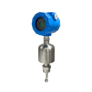
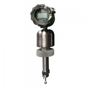
2.1.1 Vibratory Viscometers
Vibratory viscometers have become a prominent choice for in-line process monitoring due to their robust design and operational principles. The core of this technology is a solid-state sensor element that vibrates in the fluid. As the sensor shears through the fluid, it loses energy due to the fluid's viscous resistance. By precisely measuring this energy dissipation, the system correlates the reading to the fluid's viscosity.
A key advantage of vibratory viscometers is their high-shear operation, which makes their readings generally insensitive to pipe size, flow rate, or external vibrations, ensuring highly repeatable and reliable measurements. It is important to note, however, that for non-Newtonian fluids like epoxy resins, viscosity changes with shear rate. Consequently, the high-shear operation of a vibratory viscometer may yield a different viscosity than that measured by a low-shear laboratory viscometer, such as a rotational viscometer or flow cup. This difference does not imply inaccuracy; rather, it reflects the fluid's true rheological behavior under different conditions. The primary value of an in-line viscometer is its ability to track the relative change in viscosity, not simply to match an absolute value from a lab test.
2.1.2 Rotational Viscometers
Rotational viscometers determine viscosity by measuring the torque required to rotate a spindle or bob within a fluid. This technology is widely used in both laboratory and industrial settings. A unique strength of rotational viscometers is their ability to measure viscosity at various shear rates by adjusting the rotation speed. This is particularly critical for non-Newtonian fluids, like many epoxy formulations, whose viscosity is not constant and can change with applied shear stress.
2.1.3 Capillary Viscometers
Capillary viscometers measure viscosity by timing how long it takes for a fluid to flow through a tube of a known diameter under the influence of gravity or an external pressure. This method is highly precise and traceable to international standards, making it a staple in quality control laboratories, especially for transparent Newtonian fluids. However, the technique is cumbersome, requiring strict temperature control and frequent cleaning. Its off-line nature makes it unsuitable for real-time, continuous process monitoring in a production environment.
2.1.4 Emerging Technologies
Beyond the mainstream methods, other technologies are being explored for specialized applications. Ultrasonic sensors, for instance, have been used for real-time monitoring of polymer viscosity at high temperatures. Additionally, piezoresistive sensors are being researched for non-intrusive, in-situ monitoring of cross-linking and curing in epoxy resins.
2.2 Viscometer Technology Comparison
The table below provides a comparative analysis of key in-line viscometer technologies to help engineers make an informed decision based on their specific process requirements in epoxy resin manufacturing.
Table 1: Comparison of In-line Viscometer Technologies
|
Feature |
Vibratory Viscometers |
Rotational Viscometers |
Capillary Viscometers |
|
Operating Principle |
Measures energy dissipation from a vibrating probe |
Measures torque required to rotate a spindle |
Measures time for fluid to flow through a capillary tube |
|
Viscosity Range |
Wide range, from low to high viscosities |
Wide range, requires changing spindles or speed |
Suited for specific viscosity ranges; requires selecting a tube based on sample |
|
Shear Rate |
High shear rate |
Variable shear rate, can analyze rheological behavior |
Low shear rate, primarily for Newtonian fluids |
|
Sensitivity to Flow Rate |
Insensitive, can be used in any flow rate |
Sensitive, requires constant or static conditions |
Sensitive, primarily for off-line measurement |
|
Installation & Maintenance |
Flexible, easy to install, minimal maintenance |
Relatively complex; requires full submersion of the spindle; may need regular cleaning |
Cumbersome, used in off-line labs; requires strict cleaning procedures |
|
Durability |
Rugged, suitable for harsh industrial environments |
Moderate; spindle and bearings can be subject to wear |
Fragile, typically made of glass |
|
Typical Application |
In-line process monitoring, reaction endpoint detection |
Laboratory quality control, rheological analysis of non-Newtonian fluids |
Off-line quality control, standard certification tests |
3. Strategic Deployment and Optimization
3.1 Identifying Key Measurement Points
Maximizing the utility of in-line viscosity monitoring depends on selecting critical points in the production flow that provide the most valuable process insight.
In-reactor or at Reactor Outlet: During the polymerization stage, viscosity is the most direct indicator of molecular weight growth and reaction progress. Installing an in-line viscometer inside the reactor or at its outlet enables real-time endpoint detection. This not only ensures batch quality consistency but also prevents runaway reactions and avoids costly downtime from resin solidifying inside the vessel.
Post-processing and Purification Stages: Following synthesis, epoxy resin undergoes washing, separation, and dehydration. Measuring viscosity at the outlet of these stages, such as the distillation column, serves as a crucial quality control checkpoint.
Post-mixing and Curing Process: For two-part epoxy systems, monitoring the viscosity of the final mixture is critical. In-line monitoring at this stage ensures the resin has the correct flow properties for specific applications like potting or casting, helping to prevent the entrapment of air bubbles and ensuring complete mold filling.
3.2 Viscometer Selection Methodology
Selecting the right in-line viscometer is a systematic decision that requires a careful evaluation of both material properties and process environment factors.
- Material Characteristics:
Viscosity Range & Rheology: First, determine the expected viscosity range of the epoxy resin at the measurement point. Vibratory viscometers are generally suitable for a wide range of viscosities. If the rheology of the fluid is a concern (e.g., if it is non-Newtonian), a rotational viscometer may be a better choice to study shear-dependent behavior.
Corrosivity & Impurities: The chemicals and byproducts used in epoxy production can be corrosive. Additionally, the resin may contain fillers or entrained air bubbles. Vibratory viscometers are well-suited for such conditions due to their rugged design and insensitivity to impurities.
Process Environment:
Temperature & Pressure: Viscosity is extremely sensitive to temperature; a 1∘C change can alter viscosity by as much as 10%. The selected viscometer must be able to provide reliable and stable measurements in an environment with high-precision temperature control. The sensor must also be able to withstand the specific pressure conditions of the process.
Flow Dynamics: The sensor should be installed in a location where fluid flow is uniform and there are no stagnation zones.
3.3 Physical Installation and Placement
Correct physical installation is crucial for ensuring the accuracy and reliability of an in-line viscometer's data.
Installation Position: The sensor should be installed in a position where the sensing element remains fully submerged in the fluid at all times. Avoid installing at high points in a pipeline where air pockets can accumulate, which would disrupt measurements.
Fluid Dynamics: Sensor placement should avoid stagnant areas to ensure the fluid is flowing consistently around the sensor. For large-diameter pipes, a viscometer with a long insertion probe or a tee-mounted configuration may be required to ensure the probe reaches the core of the flow, minimizing the effects of boundary layers.
Mounting Accessories: Various mounting accessories, such as flanges, threads, or reducing tees, are available to ensure a proper and secure installation in a range of process vessels and pipelines. Non-active extensions can be used to bridge over heating jackets or pipe bends, positioning the sensor's active tip in the fluid stream and minimizing dead volume.

4. Closed-Loop Control and Intelligent Diagnostics
4.1 From Monitoring to Automation: Closed-Loop Control Systems
The ultimate objective of in-line viscosity monitoring is to provide the foundation for automation and optimization. A closed-loop control system continuously compares the measured viscosity value against a target setpoint and automatically adjusts process variables to eliminate any deviation.
PID Control: The most common and widely used closed-loop control strategy is PID (Proportional-Integral-Derivative) control. A PID controller calculates and adjusts a control output (e.g., reactor temperature or catalyst addition rate) based on the current error, the accumulation of past errors, and the rate of change of the error. This strategy is highly effective for controlling viscosity because temperature is the primary variable that influences its value.
Advanced Control: For complex, non-linear reaction processes like epoxy polymerization, advanced control strategies such as Model Predictive Control (MPC) offer a more sophisticated solution. MPC uses a mathematical model to predict the future behavior of the process and then optimizes control inputs to meet multiple process variables and constraints simultaneously, leading to more efficient control of yield and energy consumption.
4.2 Integrating Viscosity Data into Plant Systems
To enable closed-loop control, in-line viscometers must be seamlessly integrated into existing plant control system architectures.
System Architecture: A typical integration involves connecting the viscometer to a Programmable Logic Controller (PLC) or a Distributed Control System (DCS), with data visualization and management handled by a SCADA (Supervisory Control and Data Acquisition) system. This architecture ensures real-time, stable, and secure data flow and provides operators with an intuitive user interface.
Communication Protocols: Industrial communication protocols are essential for ensuring interoperability between devices from different manufacturers.
Build a well-designed in-line viscosity monitoring system with the help of inline viscometers, making a shift from a reactive mode of problem-solving to a proactive mode of risk prevention. Contact us right now!
Post time: Sep-18-2025


