

The Installation Mistake That Costs the Most Time
We get the call at least once a month: a plant installed a new density meter, the readings look wrong, and nobody can figure out why. After a few days of back-and-forth on process conditions and calibration settings, someone finally asks where the meter is installed.
The answer is usually something like “on the pump discharge” or “in the vertical run after the tank outlet.” Either of those is a red flag. The meter is fine. The installation is the problem.
Inline density meters are not plug-and-play instruments. They are sensitive to where you put them in the pipe. Get that wrong and you will spend weeks chasing phantom process issues. Get it right and the meter works reliably for years.
Rule 1: Horizontal Pipe Runs, Not Vertical
This is the single most commonly violated rule in density meter installation. In a vertical pipe, gravity works against you. The denser fraction of the fluid tends to concentrate at the bottom of the pipe. A density meter sampling from the bottom of a vertical run reads higher than the pipe average. One sampling from the top reads lower. Neither is representative.
In a horizontal pipe at sufficient flow velocity, the mixing is much better. Solid particles stay in suspension, liquid layers mix, and the density is relatively uniform across the pipe cross-section. For most inline density meters, a horizontal installation with the sensor at the 3 o’clock or 9 o’clock position (side of pipe) gives the most representative reading.
If your process layout makes a horizontal run impossible at the desired location, there are workarounds. A flow mixer or a static mixer installed upstream of the meter can homogenize a vertical flow enough to get a usable reading. But that adds cost and pressure drop, and it is worth considering whether a different measurement location would be simpler.
Rule 2: Straight Run Lengths Before and After the Meter
A density meter measures the density of whatever is in front of it. If the flow upstream is turbulent or stratified, the meter sees a non-representative sample. The industry rule of thumb is 5 diameters of straight pipe upstream and 3 diameters downstream. For a DN50 (2-inch) pipe, that is 250mm upstream and 150mm downstream. It sounds short, but it matters.
|
Pipe Size |
Upstream Straight Run |
Downstream Straight Run |
Notes |
|
DN25 (1″) |
≥ 125 mm |
≥ 75 mm |
Minimum for small lines |
|
DN50 (2″) |
≥ 250 mm |
≥ 150 mm |
Most common size |
|
DN100 (4″) |
≥ 500 mm |
≥ 300 mm |
Standard large line |
|
DN150 (6″) and above |
≥ 750 mm |
≥ 450 mm |
Verify with manufacturer |
What counts as a disturbance? Any fitting that disrupts the velocity profile. A 90-degree elbow in any plane. A tee junction. A valve (especially a partially open one). A reducer or expander. A pump. These all create non-uniform flow that can persist for 10-20 diameters downstream. If your elbow is 2 diameters upstream of the meter, you are measuring the distorted flow, not the process.
Rule 3: Keep It Away from the Pump — But Not Too Far
Pump suction side: bad. Pump discharge side: also risky, but for a different reason.
On the suction side of a pump, the pressure is below atmospheric. Any gas or vapor in the liquid comes out of solution and forms bubbles. Bubbles in the measurement gap of a density meter read as very low density. If you have any dissolved gas or potential for cavitation in your process, a suction-side installation will give you trouble.
On the pump discharge side, the flow is turbulent and often has some pulsation from the pump impeller. That pulsation translates to noise in the density reading. If you must install on the discharge, put it at least 10 pipe diameters downstream of the pump. That gives the flow time to stabilize.
The ideal location is in a recirculation loop or a dedicated sample line that draws from the main process and returns to the tank. This gives you full control over the flow velocity through the meter without coupling the measurement to the main process disturbances.
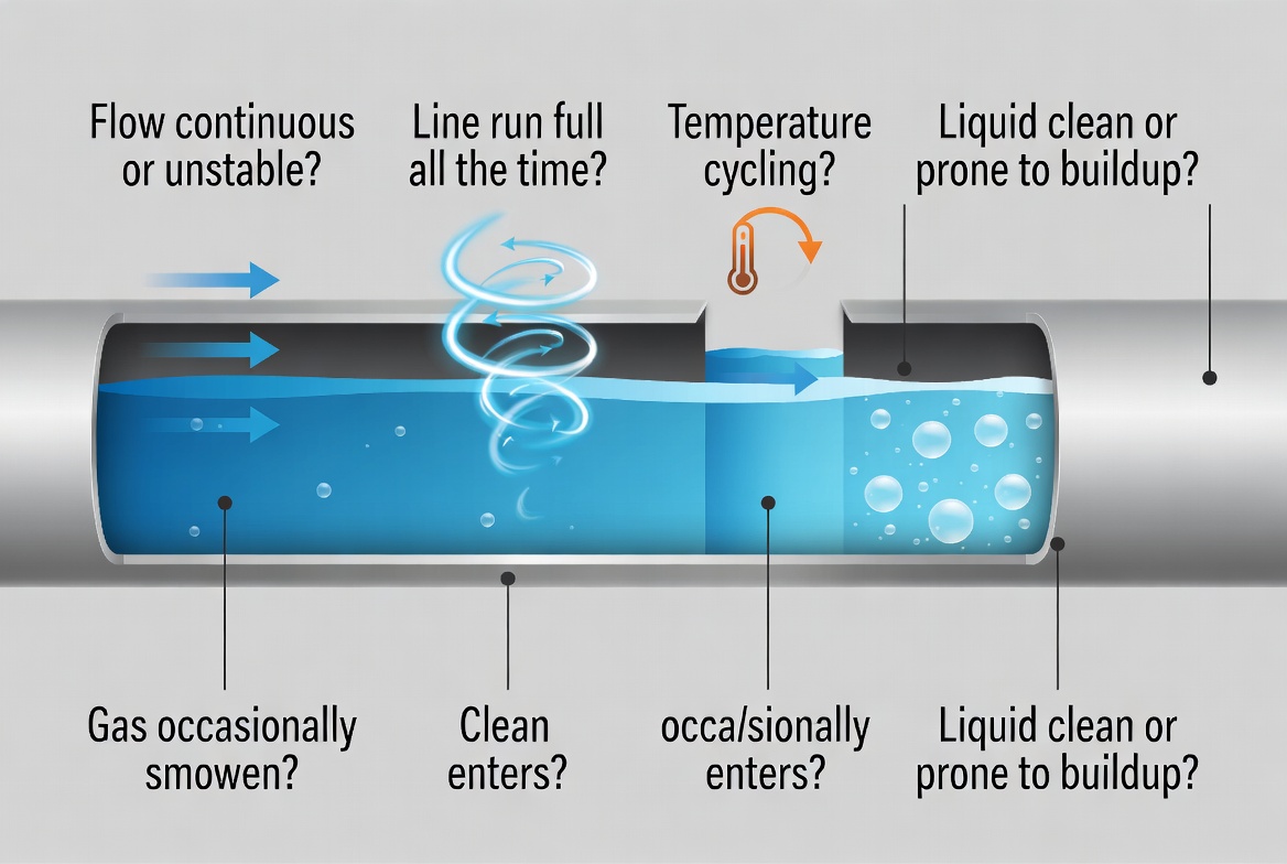
Rule 4: Flow Velocity Has to Be High Enough to Keep Solids Moving
This rule applies to any process that handles slurries, suspensions, or liquids with settling tendency. A density meter installed in a low-velocity section of pipe will see the fluid stratify. Solids settle out. The meter at the bottom reads high. The meter at the top reads low. Neither matches the blend tank.
The minimum velocity to keep most mineral slurries in suspension is around 1.5 m/s. For coarse particles or high-specific-gravity ores, it can be higher. Check against your specific ore characteristics. If the main pipeline operates at 2.0-3.0 m/s during production, the density meter location is probably fine. If the process runs at lower velocities during certain phases, consider a recirculation loop that maintains minimum flow through the meter regardless of the main process velocity.
For pure liquid processes with no solids, velocity is less critical for measurement accuracy. But it still matters for response time. A meter in a stagnant leg will not give you a real-time reading. It will give you a delayed average of whatever settled into that section last.
Rule 5: Mechanical Installation Details That Actually Matter
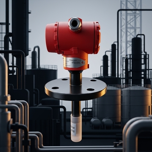
Orientation of the process connection: for a 316L stainless steel inline density meter with flanged connection, the sensor element is typically centered in the pipe bore. If the flange gasket intrudes into the flow path, it creates a localized disturbance. Use a full-face gasket or a ring gasket that sits fully within the bolt circle. Never let the gasket material protrude into the pipe bore.
Support and bracing: the density meter is heavier than a regular pipe fitting. If the piping system is not adequately supported, the weight of the meter over time can stress the gasket and cause a leak. Put a pipe support on each side of the meter, within 0.5 meters. This is especially important for DN80 and larger sizes.
Valve placement: put a full-port isolation valve on each side of the meter so it can be removed for maintenance without draining the whole pipe. A bleeder valve on one side is useful for venting gas before startup. Do not install a control valve immediately downstream of the meter — the pressure fluctuations from the valve will add noise to the density reading.
Rule 6: Electrical and Signal Wiring
The power and signal cables for an inline density meter need to be kept separate from high-voltage power cables. In most plants, the instrument signal cable runs in a dedicated cable tray or conduit. If it shares a tray with motor drives or variable frequency drives (VFDs), the electrical noise from the VFDs will couple into the 4-20mA signal and cause unstable readings.
For RS485/Modbus signals, use shielded twisted-pair cable. Ground the shield at the instrument end only — not both ends. Grounding both ends creates a ground loop that is worse than no shield at all. The cable route should avoid running parallel to high-current conductors for more than 10 meters.
If the meter is in a hazardous area, the installation must comply with the applicable explosion protection standard (ATEX, IECEx, or FM). This includes the cable entry method, the enclosure certification, and the grounding arrangement. Do not mix certified and non-certified components in the field wiring.
Checklist Before First Start-up
Before you energize the meter and start the process, walk through this list:
Pipe orientation is horizontal, sensor at 3 o’clock or 9 o’clock position.
Upstream straight run is at least 5 diameters from the nearest disturbance (elbow, valve, tee, pump).
Downstream straight run is at least 3 diameters.
Process flow velocity through the meter is within the meter’s rated range for your application.
Isolation valves are in place and bleeder valve is functional.
Pipe supports are installed within 0.5 m on each side of the meter.
Gasket is fully within the flange bolt circle, not protruding into the pipe bore.
Signal cable is in a dedicated tray, separated from VFD and motor cables.
Shield grounding: one end only, not both ends.
Hazardous area certification and grounding verified if in classified area.
Temperature and pressure are within the meter’s rated operating range.
Process baseline density recorded before startup (for future calibration reference).
LONNMETER Installation Support
The LONNMETER technical team provides installation drawings with each meter, including recommended pipe routing, support locations, and cable gland specifications. If you have a challenging installation location and want to confirm it is viable before ordering, send us the P&ID and we will review the proposed location.
For users who are already in the field and seeing unexpected readings, the first step is always to review the installation against the checklist above. Nine times out of ten, the issue is location, not the meter.
Common Questions About Density Meter Installation
Q: Can a density meter be installed on a vertical pipe?
A: Technically yes, but it is not recommended for most applications. Gravity causes stratification in vertical pipes, which means the density reading depends on where in the pipe cross-section the sensor is located. If a vertical installation is unavoidable, add a flow mixer or static mixer upstream to homogenize the fluid. Always verify that the reading matches a sample taken from a well-mixed section of the process.
Q: How close can a density meter be to a pump?
A: Never on the suction side. On the discharge side, at least 10 pipe diameters downstream. The further the better if space allows. The pulsation from a pump impeller creates noise in the density reading, and that noise is proportional to the proximity to the pump.
Q: What is the minimum straight run requirement for a density meter?
A: The general rule is 5 diameters upstream and 3 diameters downstream from the nearest flow disturbance (elbow, valve, tee). For a DN50 pipe, that is 250 mm upstream and 150 mm downstream. Larger pipes need proportionally more straight run. Always check the specific manufacturer’s recommendation.
Post time: Jun-29-2026


