

A pressure transmitter in a clean control room is a benign box. The same transmitter bolted to a natural-gas skid, a solvent-recovery column or a coal-mine face is a potential ignition source, because every electronic instrument makes heat and sparks as a by-product of doing its job. The phrase explosion proof pressure transmitter does not describe a tougher case — it describes a design contract: the instrument will not, under any fault it can suffer, release enough energy to ignite the flammable gas, vapour or dust around it. Most of the hazardous-area incidents we are asked to review after the fact were not transmitter failures. They were specification failures, where someone bought a standard industrial unit and assumed the painted aluminium housing was “safe enough,” or picked an Ex d (flameproof) device for a Zone 0 location where the rules allow only energy-limited protection. Our pressure-transmitters range already spans gauge, absolute, differential and 4-20 mA families; the hazardous-area versions are the same measurement science wrapped in a protection concept that has been tested to destruction on purpose.
Understanding that protection concept is the whole game. Two philosophies govern almost every certified unit you will meet: contain the explosion, or never let one start. Everything else — the zone, the gas group, the temperature class, the cable seal — hangs off that choice, and the choice is forced by the area classification, not by the buyer’s preference.
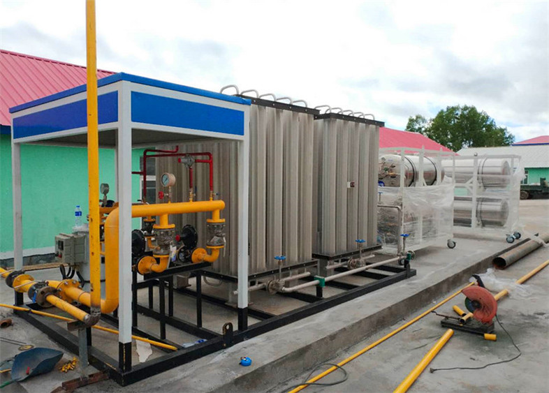
What “explosion proof” actually means
The term is loose in everyday speech and precise in standards. In the IEC 60079 series and the ATEX 2014/34/EU directive, “explosion protection” is a family of techniques, each with its own Ex symbol and its own rules. Three of them cover the vast majority of pressure-transmitter installations.
Flameproof protection, marked Ex d, is the contain-it approach. The live parts sit inside a heavy enclosure — usually cast aluminium or stainless steel — engineered to withstand an internal explosion of the local gas mixture without rupturing, and to cool the hot gases below the ignition temperature of the surrounding atmosphere before they escape through precisely machined flamepaths. The transmitter can arc, spark or even explode internally; the enclosure is built so that event stays inside. That is why an Ex d joint is a flamepath, not a gasket, and why overtightening or painting it shut degrades the protection. We covered the broader sensor vocabulary in our note on pressure sensor vs transducer vs transmitter, but the protection marking is what separates a hazardous-area unit from its office cousin.
Intrinsic safety, marked Ex i, is the never-let-it-start approach. Instead of a bomb-proof box, the circuit is designed so the energy available at any point — including a broken wire or a shorted component — is below what can ignite the weakest credible mixture. No spark, no hot surface, no ignition, by construction. Intrinsic safety is a system property, not a single device: the transmitter, the interconnecting cable and the associated apparatus (almost always a safety barrier) are certified together. A barrier that is not matched to the transmitter invalidates the whole certificate.
Encapsulation, marked Ex m, and non-sparking construction, marked Ex n, cover the remaining niches — potted electronics that cannot be reached by the atmosphere, and increased-safety assemblies where the risk of arc or spark has been designed out for less severe locations. You will see them on accessory electronics more than on the transmitter head itself, but a complete hazardous-area loop may combine several techniques across its parts.
The certificate is not a manufacturer’s promise; it is the output of a test house that, for an Ex d device, deliberately ignites the most easily ignitable gas mixture inside the empty enclosure, measures the pressure the shell must contain, and confirms the flamepaths cool the escaping products below the ignition temperature of that gas. A flameproof unit is therefore proven by being blown up on purpose, and the nameplate marking is the residue of that destructive test rather than a marketing claim. Intrinsic-safety certification works the other way: the laboratory faults every component, calculates the worst-case spark and surface energy at the hazardous boundary, and certifies the transmitter-plus-barrier-plus-cable system as a whole against the energy needed to ignite the assigned gas group.
The area classification you must read before choosing
No one selects an Ex rating in a vacuum. The installation is classified first, and the classification dictates which protection methods are legal. On the gas side, the scheme most engineers meet is the Zone system from IEC 60079-10-1. A Zone 0 location has an explosive atmosphere present continuously or for long periods. Zone 1 has it likely to occur in normal operation. Zone 2 has it unlikely and, if it occurs, only briefly. North America uses the Division system instead — Division 1 roughly maps to Zones 0 and 1, and Division 2 to Zone 2 — under NEC Article 500 and Article 505, but the underlying risk logic is the same.
Dust follows a parallel ladder: Zone 20, 21, 22 for combustible powders, fibres and flyings, with their own equipment categories. A grain elevator leg and a aluminium-powder line are dust hazards, not gas hazards, and the certification path is different even though the transmitter looks identical.
On top of the zone sits the gas or dust group, which sorts flammable substances by how easily they ignite. Mining methane is Group I. Ambient industrial gases are Group II, split into IIA (propane and most hydrocarbons), IIB (ethylene) and IIC (hydrogen, acetylene) — the hardest to protect because they need the least energy to ignite. Combustible dust is Group III. A transmitter certified only to IIA is not legal on a hydrogen line; the group rating is printed on the nameplate and it is a hard limit, not a suggestion. A sour-gas field carrying traces of hydrogen sulphide or an ethylene-oxide store both sit at the demanding end of the scale, and the certificate must name the exact gas, not only the broad group.
The final axis is the temperature class, T1 through T6, which caps the maximum surface temperature the device may reach. T6 means ≤85 °C, T4 ≤135 °C, T1 ≤450 °C. The rule is simple and unforgiving: the equipment surface temperature must stay below the auto-ignition temperature of the specific gas present. A transmitter that runs at 140 °C is perfectly fine in a T3 service and a fire risk in a T4 service. Our long-form piece on how pressure transmitters improve safety in hazardous environments walks through several real service examples; the classification table is the part engineers photocopy and pin to the panel.
Ex d versus Ex i: which protection for which zone
The zone decides the method, not the other way round, and this is where most specification errors originate.
Zone 0 — an atmosphere present all the time — permits only energy-limited protection. Flameproof Ex d is explicitly forbidden here, because a sustained explosive atmosphere means the enclosure would be called on to contain an explosion continuously, which is beyond its design. Ex i (and Ex m in limited cases) is the legal answer. Anyone who specifies an Ex d head on a Zone 0 tap has misread the area classification, and the error is found at the safety audit, not at commissioning.
Zone 1 — likely in normal operation — accepts both Ex d and Ex i. Here the buyer chooses on cost, maintenance philosophy and loop design. Ex d is a single, self-contained instrument: mount it, wire it, done, no barrier required in the field. Ex i needs the certified barrier in the safe area and disciplined cable management, but it lets you work on the loop live in many cases and it survives Zone 0 extensions of the same system.
Zone 2 — unlikely and brief — is the most relaxed. Ex d and Ex i are both fine, and “increased safety” Ex e or non-sparking Ex n variants appear here for cost-sensitive runs. A lot of tank-farm and loading-arm installations sit in Zone 2, which is why a flameproof transmitter is the default choice on those skids.
For dust, Zone 20 again demands energy-limited protection; Zone 21 and 22 accept flameproof and other enclosure techniques provided the equipment category matches. The takeaway is that the same physical transmitter can be legal in one part of a plant and a violation ten metres away, depending entirely on how the area was classified.
The practical choice between Ex d and Ex i inside a Zone 1 location usually comes down to lifecycle, not physics. A flameproof head is a sealed, self-contained item: install it, torque the joints, walk away, and the only recurring cost is the periodic visual and torque check. An intrinsically-safe loop is cheaper on the head but carries the barrier, the certified cable-energy budget and the discipline of never mixing its trays with power feeds; it repays that overhead when the same loop must extend into a Zone 0 area or when live maintenance without gas-freeing is a site requirement. Neither is “better” in the abstract — the zone and the maintenance culture pick the winner.
Gas group and temperature class are not optional
Two markings on the nameplate settle more arguments than any sales call: the group and the T-rating. A transmitter rated IIA T4 is a different legal device from one rated IIC T6, even if the pressure specs are identical, because hydrogen and acetylene (IIC) ignite with a fraction of the energy that propane (IIA) needs. We have seen procurement accept the cheaper IIA unit against an IIC line item and then discover at the hazardous-area verification that the entire run must be re-certified. The group is non-negotiable and it is checked against the actual gas, not the most common gas on site.
The temperature class is subtler because it moves with the environment. A transmitter whose surface reaches 130 °C is T4-compliant in its own right, but if the process it monitors can raise the local gas temperature, or if solar loading in a desert installation pushes the enclosure hotter than the rated ambient, the effective surface temperature can cross the line. The certificate states a maximum ambient temperature, Tamb, and the installed surface temperature is the sum of internal self-heating and that ambient. A unit rated T4 at 40 °C ambient may drop to T3 behaviour at 65 °C ambient, and a T3 rating is illegal where the gas needs T4. Sizing the protection means reading the worst-case summer ambient at the installation, not the control-room temperature.
The 4-20 mA loop and the intrinsic-safety barrier
Most hazardous-area transmitters keep the familiar two-wire 4-20 mA output, because that loop is both the power and the signal and it is easy to certify as intrinsically safe. On an Ex i installation the barrier sits at the boundary of the safe area — in the cabinet, never in the field — and it caps the voltage, current and energy that can ever reach the hazardous side. Two families exist: galvanic (isolating) barriers, which break the galvanic path and resist ground loops, and zener barriers, which are simpler and cheaper but require a carefully engineered, single-point safety earth with strict cable segregation.
The cable between barrier and transmitter is part of the certificate. Every Ex i cable has a maximum allowable capacitance and inductance, because a long run of cable stores enough energy to ignite a mixture even if the transmitter itself is benign. The installer must confirm the cable’s per-metre C and L against the barrier’s allowed values over the actual run length, and keep intrinsically-safe cables in their own tray, never bundled with power or instrument feeds. Mixing them is the classic field error that turns a certified loop into an uncertified one without anyone noticing until the audit. Our 4-20mA pressure transmitter note covers the loop math for non-hazardous duties; the hazardous version adds the barrier and cable-energy limits on top of the same 4-20 mA discipline.
Where these transmitters actually go
The application list is long because flammable processes are everywhere industry operates. A few deserve detail because the protection logic is easiest to get wrong there.
Natural-gas custody-transfer stations live in Zone 1 or Division 1, almost always Group IIB or IIC depending on the sour-gas content, with a T-class set by the lightest hydrocarbon present. The transmitter sees line pressure that can swing from near-zero to full scale across a metering run, so the span is set to the operating window with overpressure headroom, and the Ex d head carries a conduit seal to stop a gas path travelling down the armour. A differential-pressure-transmitter on the same skid often measures the orifice drop, and it carries the identical protection marking because it sits in the same Zone 1 envelope.
Chemical reactors and solvent-recovery columns add a moving target: the vapour composition changes with batch and temperature, so the designer must certify against the worst-case component, not the average. A solvent-recovery condenser handling acetone vapour needs a T-class below acetone’s auto-ignition temperature, and the group must cover the full recovered-solvent mix. This is where a single IIA rating quietly becomes inadequate the day the process runs a more volatile solvent.
Hydrogen systems — electrolysis, storage, vehicle fuelling — are IIC by definition, the highest gas group, and they also tend to run at high pressure, so the mechanical rating and the Ex rating are both pushed. Anyone who tells you hydrogen is a low-risk Group IIA gas is reading the standard backwards; hydrogen and acetylene sit at the top of the difficulty ladder and the certificate must say IIC.
Mining is its own world under Group I (methane), with the additional constraint that coal-mine equipment is certified against a specific national scheme and the ventilation-driven gas concentration is treated as permanently present in the workings. The transmitter head is Ex d or Ex i per the face classification, and the approval mark is country-specific rather than ATEX/IECEx alone.
Combustible-dust services — grain handling, metal-powder lines, feed mills — use Group III equipment in Zones 21 and 22. The hazard here is a layer or cloud of fine powder, and the protection must stop both an internal arc reaching the dust and a surface hot enough to ignite a settled layer, so the T-rating is judged against the layer-ignition temperature, which is lower than the cloud value. A transmitter that is fine for a gas service can be wrong for the same plant’s dust leg. A finely milled aluminium or maize-starch cloud ignites far more readily than the solid billet, which is precisely why the Group III rating is read from the suspended dust, never from the stored bulk.
Offshore platforms and LNG handling add a corrosive, space-constrained dimension: the transmitter must carry the Ex rating and survive a C5-M marine atmosphere, so the Ex d enclosure is often 316L rather than aluminium, and the cable entry uses double seals rated for both the explosion protection and the ingress class. A liquefied-natural-gas line also forces a low-temperature rating on the wetted parts, because the process side can sit near cryogenic temperatures while the enclosure is exposed to a temperate deck — two temperature regimes the span and the material selection must both respect at once.
Materials, corrosion and the process side
The hazardous-area rating protects the atmosphere from the instrument; the material specification protects the instrument from the process. A transmitter measuring hydrochloric acid cannot rely on a 316L diaphragm even inside a flameproof shell, because the enclosure rating does nothing for the wetted surface that actually touches the acid. For aggressive media we specify Hastelloy, Monel or tantalum sensing elements, or a PTFE-coated or ceramic diaphragm that resists both corrosion and abrasion; a sapphire-facing cell survives slurries that would erode a metal membrane within a season. The seal and the fill fluid matter as much as the protection marking: a remote seal with the wrong fill cooks the zero when the process runs hot, and a capillary that crystallizes in a stagnant leg becomes a frozen, useless link. Selecting the wetted parts is a separate discipline from selecting the method, and the datasheet carries both, because a transmitter that survives the spark but dissolves in the stream has solved the wrong problem.
A worked hazardous-area selection example
Numbers resolve the vague worry that adjectives leave behind. Take a natural-gas pressure-monitoring run on a metering skid classified Zone 1, Group IIB, T4, with a worst-case ambient of -40 to +65 °C, measuring line pressure 0 to 60 bar gauge. The 0-60 bar span uses perhaps 5:1 turndown from a 0-100 bar sensor, keeping the operating point in the upper half of the calibrated range where accuracy and long-term drift are best; the overpressure rating is set to survive a blocked impulse line at line pressure rather than the normal 60 bar, and the proof and burst pressures sit above that. Repeatability and hysteresis, not just the headline accuracy, decide how much of the temperature-class budget the measurement noise consumes. The process gas has a known auto-ignition temperature well above 200 °C, so T4 (≤135 °C surface) is comfortable on the gas side, but the +65 °C ambient plus internal self-heating must keep the enclosure below 135 °C — so the unit is specified with a T4 rating validated to at least +65 °C Tamb, not the default +40 °C. Group IIB is confirmed against the gas analysis; an IIC rating would be wasted cost here, an IIA rating would be illegal.
Protection method: Ex d is chosen because the location is Zone 1, the loop is simple, and no live maintenance is planned in the field. The 0-60 bar span is set with overpressure capability to survive a blocked impulse line at line pressure, and the 4-20 mA output drives the SCADA directly with no barrier. A conduit seal is specified at the cable entry to break any gas path along the armour, and the flamepath joints are torqued to the nameplate value and left unpainted. The result is a single self-contained instrument, legal for the zone, with no system-certification overhead. Had the same tap been Zone 0, the entire Ex d selection would be rejected and an Ex i loop with a certified barrier would be required instead — same pressure measurement, completely different protection architecture.
Cable entry and the gland that makes the mark real
The certificate covers the enclosure, but the enclosure is only as safe as the hole where the cable enters it. A flameproof Ex d cable entry is itself a certified component — typically an armoured-cable gland with a metric or NPT thread, a sealing ring and a compound-filled chamber that stops a gas path travelling down the cable armour into the head. A barrier gland serves the intrinsically-safe side, and an increased-safety gland suits the Ex e accessory. Each carries its own certificate and its own IP rating for ingress protection, and a mismatched or uncertified gland voids the enclosure mark exactly as surely as a painted flamepath. The conduit seal, the adaptor and the reducers between them are not plumbing; they are part of the explosion-protection boundary, and the auditor checks the gland certificate alongside the transmitter certificate because one without the other is an incomplete protection.
Installation and wiring mistakes that void the protection
The certificate is earned on the bench and lost in the field. A cracked or missing conduit seal reopens the gas path the Ex d design closed. Painting over a flamepath joint fills the gaps that cool the escaping gases and turns the flameproof enclosure into a torch. Overtightening the flameproof joint distorts the mating faces so they no longer register, and undertightening leaves a gap wider than the certified flamepath. Installing an intrinsically-safe transmitter with a barrier from a different manufacturer — or a different model from the same maker — breaks the system certificate even when both parts carry an Ex i mark, because the energy limits were calculated for the matched pair.
Routing intrinsically-safe cable in the same tray as power cable invites capacitive and inductive pickup that breaches the energy budget, and a double-ended earth on the safety ground creates a ground loop that can inject exactly the fault current the barrier exists to prevent. Running an Ex d unit beyond its Tamb, or mounting it where solar gain pushes the surface past the T-rating, quietly reclassifies the device below the gas requirement. None of these shows up as a transmitter fault — the reading stays correct — which is precisely why hazardous-area verification is a separate discipline from calibration.
At the verification visit the auditor reads the nameplate against the certificate, not against the catalogue. The EU-type examination number, the IECEx certificate of conformity and the national approval marks must all be present and legible, and the flamepath joint dimensions are checked with a gap gauge against the certified drawing. A unit whose marking has been painted over, or whose certificate cannot be produced, is flagged regardless of how good the reading looks, because the protection claim is what the audit protects — the measurement is assumed correct until proven otherwise, but the protection is assumed absent until evidenced. Remediation then means removing the instrument, recovering the documentation and often re-running the entire loop certification, which is why the paperwork and the torque wrench travel together to every hazardous-area job.
Large enclosures that cannot realistically be made Ex d are sometimes protected by purging and pressurisation, marked Ex p, where a clean instrument-air supply keeps the interior at a higher pressure than the hazardous area so the flammable atmosphere can never enter. That technique belongs to the junction box or analyser shelter more often than the transmitter itself, but a pressure transmitter feeding a purged enclosure still needs its own correct marking, and a failed purge alarm must be treated as the area reverting to its unmitigated classification — a detail that is easy to forget when the transmitter reading looks perfectly healthy.
A specification checklist for the engineer
Read the area classification first and write down the zone, the gas or dust group, and the required T-class before touching a catalogue. Confirm the ambient temperature range at the actual location, because Tamb moves the effective T-rating. Match the protection method to the zone: Ex i (or Ex m) for Zone 0 and Zone 20, Ex d or Ex i for Zone 1 and Zone 21, either for Zone 2 and Zone 22. Confirm the group rating covers the worst-case substance, not the most common one. For an intrinsically-safe loop, confirm the barrier is the certified partner of the transmitter and that the cable’s capacitance and inductance stay inside the allowed values over the real run length. Confirm the pressure span and overpressure rating for the impulse-line fault case, not just normal operation. And confirm the nameplate carries the marks you specified — ATEX, IECEx, and the relevant national approval such as NEC Division or GB 3836 for China — because a unit without the right mark is not a paperwork gap, it is a non-compliant instrument.
Commissioning, loop check and the as-found record
A certified transmitter still has to prove itself on the loop. At commissioning the installer drives the 4-20 mA output with a loop calibrator or a HART communicator, checks the zero and span against a deadweight or a pneumatic test pump, and records the as-found reading before any adjustment. That as-found number is the legal evidence the instrument was within tolerance on arrival; trimming a device whose as-found was already good, or skipping the loop check and trusting the bench certificate, is how a wiring fault or a mis-scaled BMS point hides behind a perfect factory paper. The barrier, the cable and the point scaling are part of the same measurement, and a hazard-area loop is only as certified as its weakest, unverified link.
What we build and what we will not claim
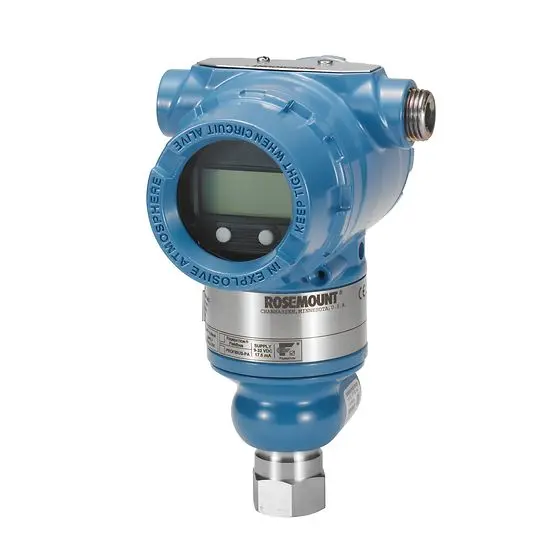
Our LONN-PT-EX family covers the hazardous-area duties most plants specify, in both flameproof (Ex d) and intrinsically-safe (Ex i) variants, built on the same sensing bench as our other pressure lines with 316L wetted parts, 4-20 mA with HART output, and a calibration traceable to national standards shipped with the as-found and as-left certificates. The coplanar and in-line platforms we already produce — such as the LONN-3051 coplanar pressure transmitter and the LONN-2088 gauge and absolute transmitter — are the mechanical basis many of these certified heads are built on, which is why the measurement behaviour will feel familiar across the range. What we will not do is quote a protection rating or an accuracy figure for a service we have not seen; the exact Ex marking, group, T-class, ambient range and performance stated for any specific model are those on its datasheet, and the numbers here describe the method and the selection logic, not a promise for an unstated application.
Every certified head leaves the bench with a documented calibration chain. The sensing element is proof-tested on a hydrostatic pressure rig, the weld seams are helium-leak checked, and the output is compared against a deadweight tester and a comparator on an ISO/IEC 17025 accredited line, so the as-found and as-left certificates trace to national standards rather than to an internal guess. That paperwork travels with the unit precisely because, in a hazardous area, the calibration and the certification are two separate promises — and both have to survive the audit.
Tell us the medium, the classified zone and group, the required T-class and the controller input, and the contact page is where the hazardous-area specification conversation starts.
Post time: Nov-06-2026


