

Differential pressure is the gap between two process pressures, and the differential pressure transmitter exists to measure only that gap — which is why it owns the filtration and level jobs a gauge cell cannot touch. Most of the failures we are called to fix on site were never transmitter failures; they were applications where the installer sized the span to a catalogue number instead of the actual head, or forgot that a closed tank has vapor pressure pushing on the top port. The differential pressure transmitter earns its place wherever the quantity you actually need is a difference: the clogging state of a filter, the height of a liquid in a sealed vessel, the load across a heat-exchanger tube bundle. Put a single-port gauge transmitter there and you are measuring the wrong number.
Stating the principle is easy; applying it correctly in the field is where applications go wrong. Inside every such instrument sit a high-pressure port and a low-pressure port. It converts the force the pressure difference exerts on a sensing diaphragm into an electrical signal — most often a 4-20 mA loop, sometimes with HART overlay — and the controller reads that signal as a level, a filter status or a flow. Only the difference reaches the diaphragm, because the two process pressures arrive on opposite sides; common-mode changes that move both ports together cancel out. That cancellation is exactly why a DP cell can read a clean tank level while the tank sits at three bar of blanket gas, or why it can flag a clogged filter without caring what the line pressure happens to be that morning.
We build the differential pressure transmitter across the same bench as our other pressure lines, and the LONN-DPT series covers the filtration and level duties most plant engineers actually specify. What follows is how those duties behave in the field, where the span math bites, and what to put on the order so the instrument arrives ready rather than almost ready.
How a DP cell turns a difference into a reading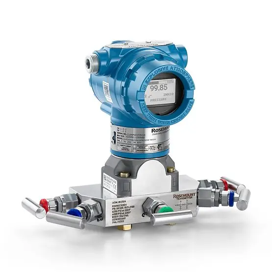
A precision diaphragm or capsule, sealed between two isolated chambers, forms the sensing element. Process fluid reaches it through impulse lines, capillary tubes or a diaphragm seal; it never touches the diaphragm directly in a sealed design. When the high side exceeds the low side, the diaphragm deflects, and a capacitive, piezoresistive or resonant element converts that deflection to a digital value. Subtracting the low-port pressure from the high-port pressure, the transmitter then applies the calibrated span and zero and drives the output. Accuracy is quoted as a percentage of the calibrated span — typically 0.065% to 0.1% on a well-specified DP cell — and it holds best when the operating range sits in the upper half of the span, not jammed against the bottom.
Reference frame matters more than buyers expect. A DP transmitter can be ordered as a simple differential device, or with one port referenced to atmosphere (that becomes a gauge function for an open-tank level), or with the low side fed from a sealed leg filled with a known fluid (that becomes a level measurement on a closed, pressurized tank). That same hardware performs three different jobs, set entirely by how you plumb the low port. Mislabeling which job you bought is the most common cause of a transmitter that “reads backwards” on commissioning day.
Filtration: the differential tells you the filter is dying
A filter does its work by blocking things, and blocking things is what raises the pressure drop across it. When the element is clean, the fluid passes with little resistance and the differential across the housing is small. As the media loads with particles, the cake builds, the restriction grows, and the differential climbs. A differential pressure transmitter mounted across the filter element is therefore a direct, live clogging gauge — long before the downstream pressure falls enough to notice, the ΔP has already told you the element is near its limit.
Mount the clean-side tap on the upstream (usually the high) port, the dirty-side or downstream tap on the low port, and the transmitter reads the drop. We size the span from the manufacturer’s clean-to-alarm pressure drop, not from the line pressure. A coalescing filter on compressed air might run 0.1 bar clean and alarm at 0.5 bar; a cartridge filter on a cooling-water line might sit at 0.2 bar and trip at 1.0 bar; a reverse-osmosis membrane sees its differential creep from a fraction of a bar toward several bar as scaling builds. Size the span to bracket that working window with headroom, so the clean reading sits low on the scale and the alarm point sits comfortably inside the top, not pinned at 100%.
Where DP filtration monitoring actually pays off
Pulse-jet baghouses are the textbook case. Each compartment’s clean-to-dirty differential tells the controls when a row of bags has blinded with dust and needs a cleaning cycle or a change-out. A transmitter that drifts low here hides a clogged compartment until emissions climb; a transmitter sized with margin keeps the cleaning logic honest. Food and beverage plants watch cartridge and membrane filters the same way to protect product and extend element life, and a brewery or dairy line that ties the ΔP alarm to a clean-in-place step avoids running a fouled filter into the batch. Compressed-air and breathing-air systems use coalescing filters whose differential is the only practical warning that oil and water are breaking through; on those services a missed alarm is a personnel and tooling risk, not just a maintenance inconvenience. Hydraulic power units, fuel-dispensing columns and lube-oil panels watch the same differential to catch element saturation before it starves a pump or a turbine bearing, and pharmaceutical WFI loops and ultrapure-water trains use it to confirm a membrane has not fouled between sanitizations.
The mistake we see most is ordering a DP cell with a 0-10 bar span to monitor a 0-0.5 bar filter drop because “it’s the same range as the line.” The result is a reading where the useful 5% of the scale carries the entire decision, accuracy collapses into the noise, and the alarm chatters or never trips. Match the span to the differential, not to the pipeline.
Level by hydrostatic head: open and closed tanks
Level is the second natural home of the DP transmitter, and it rests on one equation: the pressure at the bottom of a liquid column equals the liquid density times gravity times the height. ΔP = ρ · g · h. Reading the pressure the column exerts, the transmitter lets the controller report height once the density is known. What sits on top of the liquid, and what sits between it and the port, is the subtlety.
On an open tank the vapor space is atmosphere, so a gauge transmitter on the bottom tap reads the hydrostatic head directly and translates it to level through the liquid density. No low-port complication, no blanket gas to subtract. Cone-roof atmospheric tanks, floating-roof gasoline storage and pressurized propane bullets each impose a different leg decision, and a sphere or a horizontal vessel changes the impulse-line routing as much as the fluid does. Density is the catch: the same head means different levels for water, for a 1.2 SG syrup, or for a tank that holds two liquids of different density in layers. Without the calibrated density actually present in the tank, the transmitter cannot report a true height.
On a closed, pressurized tank the vapor above the liquid also presses on the bottom port, and the transmitter would over-read the level by exactly that vapor pressure unless the low port sees the same vapor. Run an impulse line or a sealed leg from the top of the tank to the low port and the transmitter now reads only the column — the vapor pressure cancels because it arrives on both sides. This is the wet-leg or dry-leg arrangement, and it is where most DP level installations live.
Wet leg, dry leg and the zero math
A dry leg is just an open impulse line down from the top vapor space to the low port; it works when the vapor does not condense in the line. A wet leg is that same line permanently filled with a known reference liquid — often glycol or a silicone fill — so condensation can never change the low-side pressure. Each reference fluid carries its own density, and the maths must account for the column of wet-leg fluid hanging below the low port. Ranging then uses “zero elevation” (the wet leg adds a standing negative offset) or “zero suppression” (the taps sit above the zero level and a standing head must be subtracted). Get the sign wrong and the tank reads full when empty.
We routinely see installations where the wet-leg fill fluid was chosen for availability rather than density stability across the operating temperature. As the fill expands or its density shifts with the season, the zero drifts and the operator re-zeroes by hand every few weeks. Specifying a fill fluid whose density and thermal behaviour are documented over the tank’s temperature range — and matching the capillary length so the offset is computed, not guessed — removes that recurring nuisance. The differential pressure transmitter itself is rarely the variable; the fill fluid and the leg length are.
Interface and density measurement without a second instrument
A less obvious use is interface level: two immiscible liquids of different density sharing a tank, with the heavier below the lighter. A DP cell spanning the interface zone reads the total head, and because the two layers have different densities, the pressure at a fixed tap changes as the boundary moves. With both densities known, the interface position is solvable from the single differential reading. The same trick, run on a fixed geometry, gives bulk density: as the average density in the column changes, the differential shifts, and the transmitter reports it. Crude-oil desalters, acid-alkali settlers and separator vessels use exactly this, and it is a cheaper answer than a nucleonic or a dedicated interface probe when the densities are well characterized.
One honesty caveat never changes: the calculation assumes the two densities you entered are the two densities present. An incoming batch whose composition differs quietly invalidates the interface math, and the transmitter will report a confident, wrong number. No instrument beats the densities loaded into the controller.
Seal systems: when the process cannot touch the impulse line
Many media corrode, freeze, crystallize or silt in an open impulse line, and then the line itself becomes the failure. A diaphragm seal with a remote capillary moves the sensing diaphragm away from the process and fills the connecting capillary with a stable fluid, so the transmitter body stays clean and the process stays out of the impulse path. On a filter housing handling aggressive or polymerizing fluid, or a tank holding a liquid that freezes in a stagnant leg, the seal is not optional — it is what makes the measurement survive the week. A flush seal with a barrier fluid keeps the process off the diaphragm on a sour-gas or slurry line, a welded all-316L face survives a caustic scrubber where a screwed seal would weep, and a remote seal with a flexible capillary reaches a reactor agitator or a boiler drum that no fixed sensor can mount against.
Seals add their own error budget. Capillary fill carries a density and a temperature coefficient; a long capillary at a different temperature than the transmitter introduces a thermal zero shift that grows with length and with temperature difference. We keep capillary runs short and spec the fill for the service temperature, and on hot duties we sometimes route the capillary to balance the transmitter and seal temperatures rather than bury it in a hot bundle. A pressure-transmitter line that reads true at the bench and lies at the pipe is almost always a seal or leg problem, not a sensor problem.
Range sizing that survives commissioning
Sizing the span is where good intentions meet bad numbers. Calibrate the span to sit just above the maximum operating differential with a margin for surge, and the overpressure rating must cover the worst-case single-port exposure during start-up, not the normal differential. A filter DP cell sees only a fraction of a bar in service but can see the full line pressure on one port if an isolation valve is closed on the other; the sensor must withstand that without a shift, or the next reading is compromised even after the pressure relieves.
We ask for the operating differential, the line pressure, the maximum permissible overpressure, the process temperature, the media and the wetted-material need before we name a model. On a closed-tank level job we also need the vapor density and whether condensation is expected, because those decide wet leg versus dry leg and the fill fluid. The 4-20mA pressure transmitter sibling we build for direct pressure duties shares the same loop discipline, and the two often sit on the same skid — one watching line pressure, one watching the filter or the level — which is why a consistent 4-20 mA and HART convention across both keeps the BMS point mapping sane.
Response, damping and the noisy filter signal
A DP cell on a pulsing line — a positive-displacement pump, a compressor discharge, a baghouse cleaning pulse — sees pressure spikes that are real but meaningless to the level or filter decision. A damping filter on the transmitter smooths the output over a settable time constant so the controller sees the trend, not the ripple. Set it too low and the alarm chatters on every pulse; set it too high and a genuine rapid change is flattened into a lag. Finding the right value happens on the actual line during commissioning, not by copying it from another service.
Here the 4-20 mA live zero also earns its keep. A broken loop or a dead transmitter drives the signal to below 3.6 mA, and the controller flags a fault instead of trusting a frozen reading. On a filtration duty where a stuck-high differential could mask a burst element, that fault path is the difference between a logged event and a contaminated downstream stream.
A worked closed-tank level example
Numbers settle arguments that adjectives start. Take a closed solvent tank, 4 metres tall, holding a liquid at 0.85 SG, blanketed with nitrogen at 1.5 bar gauge, with a wet leg of the same height filled with a 1.1 SG reference fluid. At full, the liquid head is ρ·g·h = 0.85 · 1000 · 9.81 · 4 ≈ 33.4 kPa. At empty the transmitter still sees the wet-leg column on the low side, 1.1 · 1000 · 9.81 · 4 ≈ 43.2 kPa, so the calibrated zero must be elevated by that amount — the transmitter reads −9.8 kPa at empty and +23.6 kPa at full, a 33.4 kPa span. Blanket pressure of 1.5 bar never enters the reading, because it loads both ports equally and cancels. Spec the span as 0 to 33.4 kPa with a zero elevation of 9.8 kPa and the controller reports tank level directly, provided the liquid density stays at 0.85; a batch at 0.80 would read a level about 6% high, which is why the composition note in the controller matters more than the transmitter’s own specification.
Installation errors that masquerade as transmitter faults
Leave the equalizing valve cracked open and you get the classic fault. It connects the high and low ports through the manifold, the differential collapses to near zero, and the tank reads empty while it is full — the transmitter is reporting exactly what it sees, and the fault is upstream of the sensor. Swap the high and low impulse lines at the manifold and the reading climbs as the tank drains — the mirror image of truth — and it survives factory checkout because nobody checked the port labels against the taps. An unvented high leg on a wet-leg service traps gas that compresses with temperature and shifts the zero by a few percent every season. A seal capillary routed through a hot tray while the transmitter sits in the cold reads a thermal zero error that grows with the temperature difference, not with the level. Each of these is fixed with a wrench or a routing change, never with a new transmitter, which is why the first question on a “faulty DP cell” call is always about the legs and the manifold, not the sensor.
Filtration alarm philosophy and maintenance timing
Across a filter, the differential is a maintenance clock, and the alarm points should be set from the element manufacturer’s data, not from a round number. A pre-alarm at 60% of the clean-to-dirty rise gives operations time to schedule a change during a planned window; a trip at 90% protects the downstream equipment or product from a burst or blinded element. Between those points the transmitter’s job is steady trending, and a damping value tuned on the live line keeps the pre-alarm from chattering on pump pulses. Where the filter protects a critical stream — breathing air, a food line, an RO train — the alarm should latch and surface to the operator rather than bury in a trend, because a missed filter alarm is rarely recoverable downstream. Watching line pressure on the same skid, the pressure-transmitter is a useful cross-check: a filter clogging while line pressure falls points to a pump or supply issue, not the element, and distinguishing the two from the two readings prevents a needless element change-out.

A specification checklist for the engineer
Confirm the reference frame first — differential, gauge-by-open-low-leg, or sealed-leg level — because the same hardware is ordered three different ways and the wrong one reads backwards. Confirm the span brackets the working differential or head with headroom, not the line pressure. Confirm the overpressure rating covers single-port exposure during isolation and start-up. Confirm whether the service needs a diaphragm seal and, if so, the fill fluid and capillary length to match the temperature range. Confirm the densities loaded into the controller are the densities actually present, for both level and interface maths. Confirm the loop is 4-20 mA with the correct shunt or HART load, and that the BMS point is scaled to the nameplate rather than an assumed range. And confirm the calibration reference reaches the site at commissioning, because a transmitter checked against a hope reads like one.
What we build and what we will not claim
Our LONN-DPT series covers the filtration and level spans most plants need, with diaphragm-seal and remote-capillary options for corrosive, freezing and silting media, and 4-20 mA plus HART output for direct controller integration. We calibrate each unit against a deadweight or comparator traceable to national standards and ship with the as-found and as-left certificates. What we will not do is quote a performance number for a service we have not seen; the accuracy, range and material grades stated for any specific model are those on its datasheet, and the figures here describe the method, not a promise for an unstated application.
Tell us the medium, the working differential or head, the line pressure and the controller input, and the contact page is where the specification conversation starts.
Post time: Nov-04-2026


