

Why Lubricant Quality Comes Down to Two Numbers
Lubricant specification sheets list a dozen properties: flash point, pour point, TAN, water content, ash content, and more. But in the blending process itself, the two numbers that tell you whether the batch is right are density and viscosity. Everything else is either a formulation input or a quality verification done in the lab after blending.
Viscosity is the primary functional property. It determines how the lubricant flows at operating temperature. Too thick and you get high startup torque, poor cold-start performance, and excessive friction. Too thin and the oil film breaks under load, leading to wear. The viscosity grade (ISO VG 32, 46, 68, for example) is the most critical specification for an industrial lubricant.
Density is a quality indicator, not a functional specification — but it is one of the fastest checks you can run in the plant. If the density is wrong, either the base oil composition is off or the additive package is wrong. Density drift during blending is often the first sign that something is going wrong.
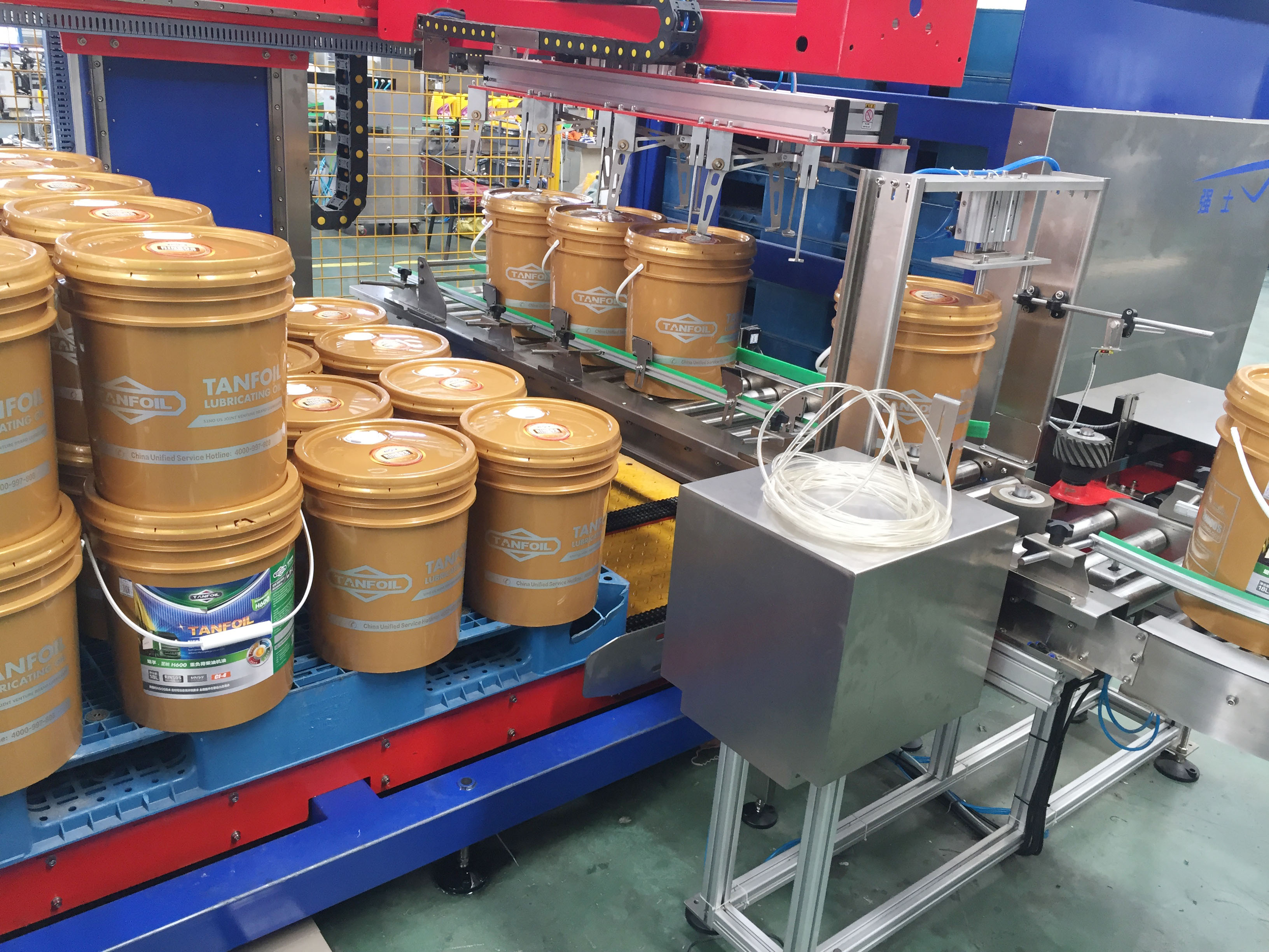
Where Viscosity Measurement Fits in the Lubricant Process
Most lubricant blending plants batch-blend from base oils and additive packages. The base oils come from the refinery with a defined viscosity. The additive package adjusts performance. When you combine them, the resulting viscosity is a weighted average — roughly, but with the non-linear mixing behavior that means you need to actually measure it.
The blending control loop typically works like this: the operator sets a target viscosity. As base oil and additives are charged into the blend tank, an inline viscometer monitors the viscosity in real time. When the reading reaches the target, the inlet valves close. This is faster and more accurate than waiting for a lab sample.
For most industrial lubricants, viscosity is measured at 40°C or 100°C. The measurement temperature matters because viscosity drops sharply as temperature rises. An inline viscometer needs temperature compensation to give a stable reading across the blending cycle, especially if the blend temperature varies between batches.
Why Inline Viscosity Beats Lab Sampling for Blending Control
A lab viscometer gives you an accurate result. The problem is turnaround time. A typical kinematic viscosity measurement in the lab takes 15 to 30 minutes for the bath to equilibrate and the measurement to complete. In a blending process that takes 20 to 40 minutes total, waiting for the lab means you are controlling based on the last batch, not the current one.
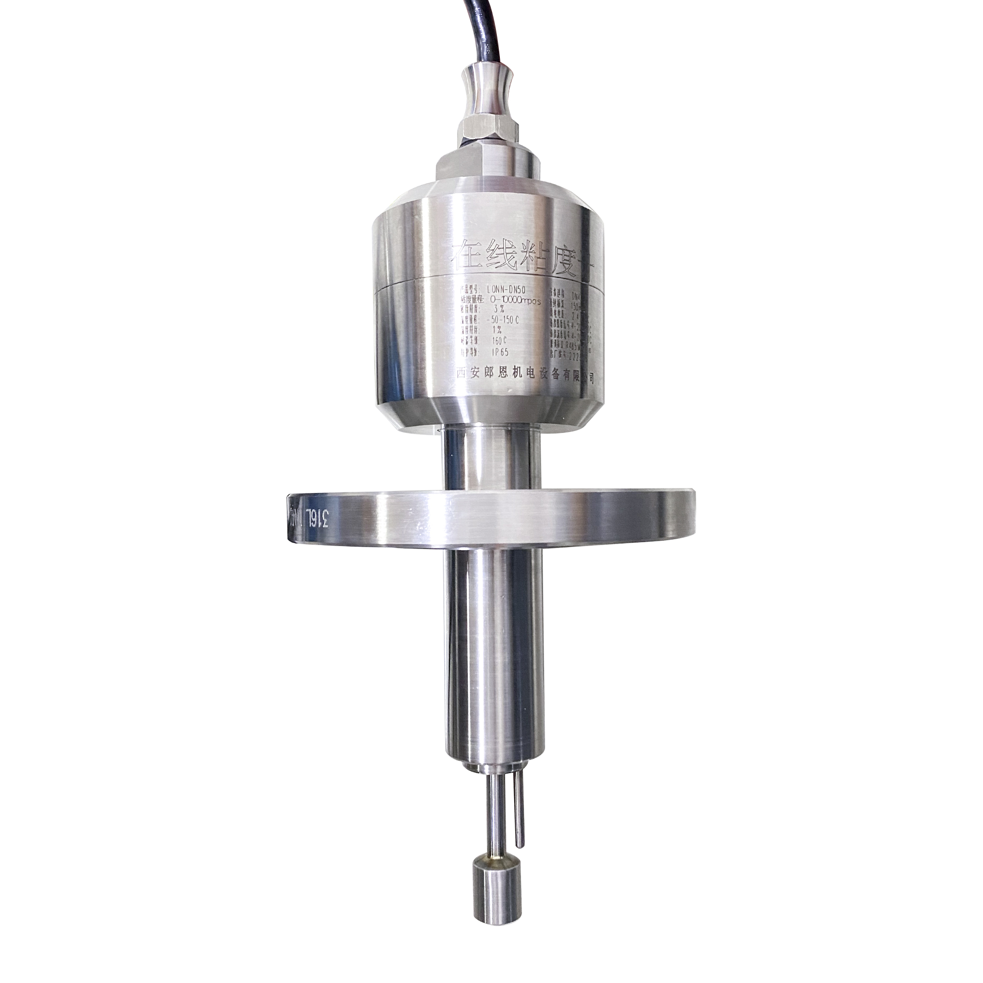
Inline viscosity measurement closes that gap. A vibrational viscometer (tuning fork or vibrating cylinder) mounted in the blend tank or the transfer line gives a reading every second. The blending valve responds to the live signal, not the lab result. Overfill of viscosity is reduced, which means less rework.
We have seen plants go from a viscosity hold-out rate of 8-10% of batches to under 1% after switching to inline control. That number is real — it represents the difference between treating the viscometer as a process instrument versus a quality check.
Density as a Blend Integrity Check
In a blending plant, density measurement does two jobs. First, it verifies that the base oil being charged matches the expected feedstock. If the supplier changed the base oil source and the viscosity index improver grade changed, the density will shift before the viscosity shows it.
Second, for additive packages that are density-sensitive, density monitoring confirms that the additive is properly mixed. A density gradient in the blend tank — denser at the bottom — tells you the mixing is incomplete.
The practical range for lubricant density is roughly 0.82 to 0.92 g/cm³ at 20°C. A density meter with ±0.001 g/cm³ accuracy is sufficient for blend integrity checking. You are looking for a shift of 0.005 to 0.010 g/cm³ from the target, which is five to ten times the meter’s resolution.
Lubricant Types and Their Measurement Requirements
|
Lubricant Type |
Viscosity Grade |
Density Range |
Key Measurement |
Instrument |
|
Hydraulic oil |
ISO VG 32–68 |
0.85–0.88 g/cm³ |
Viscosity + density |
Viscometer + density meter |
|
Gear oil |
ISO VG 150–220 |
0.88–0.91 g/cm³ |
Viscosity (primary) |
Viscometer (high range) |
|
Turbine oil |
ISO VG 32–46 |
0.85–0.87 g/cm³ |
Viscosity + moisture |
Viscometer + online water sensor |
|
Compressor oil |
ISO VG 68–100 |
0.87–0.90 g/cm³ |
Viscosity + density |
Viscometer + density meter |
The Additive Package Complication
Base oils are simple to measure: viscosity and density are well-behaved and predictable. Additives are not. Viscosity index improvers, pour point depressants, anti-wear additives, and detergents all affect the viscosity in ways that are not always linear with concentration.
A VI improver is the most problematic. It is a polymer that thickens the oil at high temperature but has less effect at low temperature. The result is that the viscosity measured at 40°C or 100°C does not fully represent the in-service performance. The lab uses a multi-temperature viscometry to compute the VI (Viscosity Index). The inline viscometer gives you the process control number, not the specification number.
For inline control, the practical approach is to calibrate the inline viscometer against the lab method for your specific formulation. Once that correlation is established, the inline reading tracks the batch quality reliably. Recalibrate when the formulation changes.
LONNMETER Instruments for Lubricant Quality Control
The LONNMETER LONN-V100 inline vibrational viscometer handles the viscosity range of most industrial lubricants (2 to 1,000 mPa·s) with a response time under 2 seconds. Temperature compensation is built in. The output is 4-20 mA or Modbus RTU.
The LONN-DN100 inline density meter covers the lubricant density range (0.82 to 0.92 g/cm³) with accuracy to ±0.001 g/cm³. For blending control, both instruments can be mounted in the blend tank or in a bypass loop.
If you are specifying inline instrumentation for a lubricant blending plant and want to discuss viscosity range, measurement temperature, or the correlation approach for VI-improver formulations, the LONNMETER team can review your process and recommend the right configuration.
Frequently Asked Questions About Lubricant Measurement
Q: Can one instrument measure both viscosity and density?
A: Not in one sensor — viscosity and density are different physical properties that require different measurement principles. Most lubricant plants run two separate instruments: a viscometer and a density meter. Both feed the DCS or blending control system.
Q: How does temperature affect viscosity measurement in lubricant blending?
A: Viscosity drops exponentially as temperature rises. A change of 5°C in blend temperature can shift the reading by 5-10% for many lubricants. An inline viscometer with integrated temperature compensation converts the reading to the reference temperature (usually 40°C or 100°C) so the blending control is not affected by normal temperature variation.
Q: What viscosity range do I need for industrial lubricant blending?
A: Most industrial lubricants fall between ISO VG 32 and ISO VG 220, which translates to roughly 30 to 220 mm²/s at 40°C (or 5 to 40 mPa·s in dynamic viscosity). Gear oils and heavy industrial oils run up to ISO VG 680. Verify that the viscometer covers the full range of products you blend.
Q: How do I handle VI improver polymers that make viscosity non-linear?
A: Calibrate the inline viscometer against the lab kinematic viscosity method for your specific formulation. The calibration curve compensates for the non-linearity. When the additive package changes, recalibrate. Do not assume that a calibration for one formulation works for another.
Post time: Jul-10-2026


