

A mid-size chlor-alkali and specialty chemical plant in southern China ran its tank farm on magnetostrictive float gauges and wet-leg differential pressure transmitters for eight years, and by year seven the maintenance log read like a confession. Float stems seized in viscous caustic, differential cells zero-shifted every time the impulse line crystallized, and the only number the control room trusted was the one a technician read off a dip tape through a manhole. We were called in to put a non-contact instrument on seven atmospheric storage tanks, and the instrument that left on the truck was our LONN-ULM ultrasonic level meter. This is what the deployment actually looked like after twelve months on the roof, including the two problems nobody put in the original quote.
The plant and what it was trying to measure
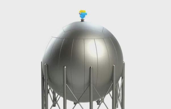
The tank farm held seven atmospheric vertical cylinders, each eight metres tall and roughly twelve metres in diameter, standing in an open yard exposed to a subtropical summer. The liquids were low-volatility process streams: a 32% sodium hydroxide solution, an ethylene glycol blend used for heat-transfer loops, a demineralized water stream dosed with a corrosion inhibitor, and a couple of intermediate surfactant solutions. Nothing in that list boils or flashes at ambient pressure, and the surfaces sat calm except after a transfer pump kicked in. The operating temperature swung from 5 °C in winter to 35 °C in summer, and the headspace above each liquid was ordinary humid air, not a vapour blanket.
That profile — calm surface, low vapour pressure, no agitation, a measurable but honest temperature gradient — is exactly the envelope where an ultrasonic meter stops being a compromise and becomes the right call. The plant needed a reading it could reconcile against the tank strapping table during a monthly inventory audit, and it needed the reading without a technician climbing a cage twice a week.
Why the old method was failing
The float gauges failed quietly and expensively. A magnetostrictive stem sitting in 32% caustic slowly stained and stuck where the liquid line crept up and down, so the reported level lagged the true level by a hand span and nobody noticed until a transfer overfilled. The wet-leg differential pressure transmitters were worse in a different way: caustic crept into the impulse line, crystallized on the cold days, and forced a zero re-trim that drifted again within a month. Both instruments had a wetted part that the liquid could attack, and both needed a shutdown window to service.
The manual dip tape was the safety problem, not the accuracy problem. Reading a tank meant opening a manhole on a hazardous-area roof, lowering a steel tape past a corrosive mist, and writing the number in a book. The plant’s own permit-to-work rules treated that as confined-space-adjacent entry, so it happened on a schedule, not when inventory needed it, and the data was always a day old.
Why ultrasonic, and why not radar or float
We walked the same selection path the plant should have walked before buying anything. A float instrument puts a moving part in the most corrosive place in the system — the liquid itself — so it was disqualified on maintenance grounds for the caustic and glycol tanks. Radar was the honest alternative, and on one tank it won: a small buffer holding a light aromatic solvent with enough vapour pressure that an ultrasonic beam would have lost energy to the headspace and returned a soft, wandering echo. That tank got a radar level transmitter instead, and it has held since. For the other six tanks the surface was calm, the vapour was negligible, and radar would have spent three times the money on a property the application never used.
So the answer was ultrasonic for six, radar for one. That split is the whole point of a proper selection: pick the principle against the liquid and the gap, not against the catalogue.
The LONN-ULM configuration we supplied
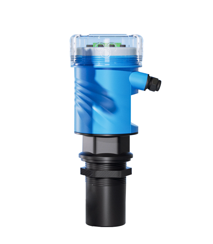
Each LONN-ULM ultrasonic level meter shipped as a top-mounted transducer with a PVDF face — PVDF because it shrugs off caustic and most solvents without the chemical attack that destroys a bare piezoceramic. The transducer ran at 120 kHz, a frequency that keeps the beam tight enough to ignore the ladder rung and the dip pipe without narrowing the measurement range on an eight-metre tank. Output was 4–20 mA with HART riding the same pair, because the plant’s distributed control system already spoke HART and nobody wanted a second bus.
The tank farm sat in a classified hazardous area, so every unit carried a flameproof Ex d enclosure and the cable entries used sealed glands rated for the zone. Ingress was IP67 for the outdoor roof, and an integrated temperature sensor lived in the transducer face to feed the speed-of-sound correction. Stated accuracy was ±3 mm, and the stated range was 0.3 to 15 m — comfortably covering an eight-metre tank with margin on both ends.
The installation realities nobody budgets for
Mounting height decided the dead zone, and the dead zone decided whether the high alarm was real. The transducer sits a measured distance above the high-level alarm setpoint, and the meter physically cannot see the first 0.4 m beneath its face. On an eight-metre tank a 0.4 m dead zone forfeits one twentieth of the span before the liquid even reaches a risky height — small, until you realize the high alarm was planned at 0.35 m below the nozzle. We caught that on the draft layout, dropped the nozzle mounting point, and recovered the alarm. A dead zone drawn on paper after commissioning is a blind spot you cannot fix without cutting steel.
The other un-budgeted item was the cable gland. A flameproof certificate on the enclosure means nothing if the conduit entry was never sealed, because the rating lives or dies at the gland. We flagged the sealing on every hazardous-area drawing we returned with the quote, and the plant’s electricians sealed to the zone class before the first unit went live.
How the meter actually finds the surface
An ultrasonic meter is not a tape measure with a speaker. The transducer launches a burst, listens for the first strong return, and timestamps the round trip; the instrument then converts that time into a distance by dividing by twice the corrected speed of sound. The engineering lives in what happens between the launch and the timestamp. On a calm tank the true surface is the first big echo, but the beam also sees the tank wall, the nozzle edge and any internal steel, and each of those returns a smaller echo at a fixed distance. The signal processor ranks the echoes, rejects the ones that sit inside the blanking window or never move, and locks onto the one that behaves like a liquid surface — present at the right distance, stable frame to frame, and responsive when the level changes.
That ranking is why averaging and damping matter. We set the averaging window against the wave slap on an open channel and the damping against the froth flutter on a fermenter; on these calm chemical tanks the window was short because the surface barely moved, but we still left enough damping to ignore a bird landing on the roof. The relay hysteresis was set against the pump cycling on a buffer tank so the high-high alarm did not chatter when the level hovered at the setpoint. None of those numbers are catalogue defaults — they are set against the tank, and they are the reason the reading in the control room matched the strapping table a month later.
The temperature-gradient correction that saved the reading
This is the part of the job that separates a reading from a guess. Sound moves through air at a speed set by the gap temperature, and the relationship is unforgiving: the speed of sound in air is roughly c ≈ 331.3 + 0.606·T metres per second, so every degree the gap warms or cools shifts the speed by about 0.6 m/s. On an eight-metre tank that is roughly six millimetres of range error per degree Celsius.
An outdoor tank in southern China does not hold one temperature. On a summer afternoon the vapour column sitting over a 30 °C liquid can run 15 to 25 °C hotter near the transducer than at the surface, and a single face-mounted sensor corrects against the wrong number for the top slice of the path. Left uncorrected, that gradient alone pushed the reading off by 90 to 150 mm — enough to fail an inventory audit and to mistrust the instrument entirely.
We solved it the boring way: on the gradient tanks we dropped an immersed resistance thermometer to mid-gap and fed the real average gap temperature into the calculation instead of the face reading. The error against the tank strapping table dropped below 3 mm, which is to say below the instrument’s own specification. The correction is not a catalogue default; it is a field decision made against the actual temperature profile, and it is the difference between a meter that reads and a meter that lies.
Condensation on the transducer and how we handled it
A humid tank farm after a cool night throws condensation onto any cold surface, and the PVDF face of an ultrasonic transducer is exactly such a surface. A film of water on the face creates a false echo at a fixed near distance that can mask the true surface return, and the first symptom is a reading that climbs a few centimetres and sticks. Two of the seven tanks had a saturated headspace after a transfer, so we specified a self-purging air collar on those two: a slow purge of instrument air across the face keeps the condensation from ever forming a continuous film. The other five tanks ran a periodic auto-zero routine that re-baselined the near echo during a confirmed empty window.
Neither fix is exotic, but both belong in the specification, not in the service call. A coated transducer that drifts is a calibration fault only until you wipe it — then it was never a calibration fault at all.
Commissioning and the false echoes we had to blank
One tank carried a dip pipe and a vertical ladder rung inside the cone of the beam. A 120 kHz beam on that nozzle was narrow, but not narrow enough to ignore a steel rung a metre below the face. The first commissioning scan returned a strong secondary echo at a fixed distance, and the meter briefly locked onto it during a low-level swing. We set an interference blanking window around that distance — the meter ignores returns inside the blanked band and reports only the surface — and the false target disappeared from the log.
The lesson is not that the beam was wrong; it is that every internal obstruction has to be on the layout before release, because blanking is a fix you apply after you know where the obstruction is, and you only know after you look.
The seven tanks, line by line
The deployment was not one instrument repeated seven times; it was seven different liquids, temperatures and obstruction profiles under one specification. The table below is the as-built record the plant now keeps with the drawings.
| Tank | Liquid | Height | Instrument | Note |
| T-01 | 32% caustic soda | 8 m | LONN-ULM ultrasonic | PVDF face, purge collar, dual-RTD gap correction |
| T-02 | Ethylene glycol blend | 8 m | LONN-ULM ultrasonic | Calm surface, face sensor only |
| T-03 | Demineralized water + inhibitor | 8 m | LONN-ULM ultrasonic | Low conductivity, no correction needed |
| T-04 | Surfactant solution A | 8 m | LONN-ULM ultrasonic | Saturated headspace, purge collar fitted |
| T-05 | Surfactant solution B | 8 m | LONN-ULM ultrasonic | Dip pipe inside cone, blanking window set |
| T-06 | Light aromatic solvent | 8 m | Radar level transmitter | Vapour pressure forced the change |
| T-07 | Intermediate glycol blend | 8 m | LONN-ULM ultrasonic | Calm, low-vapour, face sensor only |
Six ultrasonic units and one radar unit, all on the same hazardous-area roof, all reading into the same distributed control system. The split is the proof that the selection ran on the liquid and the gap, not on a single favourite technology.
Results after twelve months
Twelve months in, the six ultrasonic units held ±3 mm against the tank strapping table during the monthly audit, which is to say they matched the tape without anyone opening a manhole. The float gauges and wet-leg cells were retired, and the maintenance cadence dropped from quarterly strip-downs to an annual visual check of the transducer face and the gland seal. The manual dip was eliminated entirely, which the plant’s safety officer counted as the real win — no more permit-to-work entries on a corrosive roof.
The one radar level transmitter on the solvent buffer performed as predicted, confirming the split decision. Total installed cost for the six ultrasonic units came to roughly a third of what seven radar units would have cost, and the labor and downtime saved on float and wet-leg service paid the deployment back in about fourteen months. The plant’s instrument engineer now specifies ultrasonic as the default for any calm, low-vapour atmospheric tank in the yard, and radar only where the vapour or the dielectric constant forces it.
During the monthly reconciliation the plant compared the ultrasonic reading against the tank strapping table — the calibrated volume-versus-height curve stamped on the tank shell — across a full year of fill and draw cycles. On the caustic and glycol tanks the ultrasonic tracked the strapping table to within ±3 mm through summer and winter, which the audit signed off without a single manual correction. The surfactant tanks, the two with the purge collars, held the same tolerance once the condensation was kept off the face. The one deviation the year produced was a transient on T-05 during a transfer, when the dip pipe returned a competing echo; the blanking window already covered that distance, and the meter never reported it as level.
The safety and labor case, quantified
The accuracy story is the one the audit rewards, but the plant booked the money on labor and safety. Retiring the float gauges and wet-leg cells removed two quarterly strip-downs per tank, which on seven tanks was fifty-six service windows a year that no longer needed a confined-space permit, a two-person team, and a shutdown of the transfer line. The manual dip tape disappeared entirely, which removed the single most exposure-heavy task on the roof — lowering a steel tape past a caustic mist through an open manhole. The plant’s own hazard review counted that task as a top-three routine risk in the tank farm, and deleting it was worth more than the instrument saving.
The remaining labor is one annual visual check per transducer, a glance at the gland seal, and a confirmation that the purge collar is still breathing. That is a morning of work for the whole farm, against the better part of a week the old regime consumed — and the week was the one with the permits and the risk, not the quiet morning.
Calibration and what we keep on file
Every LONN-ULM left the bench with a traceable calibration certificate referenced to a national length standard, because the audit that signs off an inventory reconciliation will ask for the certificate before it asks for the display. We keep the as-found and as-left values on file for each unit, re-issue the certificate on the annual visual, and treat the gap-temperature correction curve as a calibrated input rather than a setting. The point is not paperwork; it is that a level number used for custody-style reconciliation has to survive a third party’s questions, and a certificate is the only answer that holds.
What we would do differently
If we re-ran the job, two changes would go in the original specification rather than the lesson log. First, the dual-resistance-thermometer gap correction would go on all seven outdoor tanks from day one, not just the ones we later measured as gradient-heavy — the gradient showed up on every tank once we looked, just by different amounts. Second, the purge collar would go on every tank with a saturated headspace after transfer, which turned out to be more than the two we guessed. Both are cheap to specify and annoying to retrofit.
Lessons for specifying ultrasonic in chemical tanks
- Name the liquid’s vapour pressure before anything else; low volatility is the gate that lets ultrasonic in.
- Draw the dead zone against the high and low alarm setpoints on the layout, not after the nozzle is welded.
- Correct the speed of sound against the real gap temperature, and on an outdoor tank that means a measured gap profile, not a face sensor alone.
- Treat condensation on the transducer face as a specification item, with a purge collar or an auto-zero routine, not a surprise service call.
- Put every internal obstruction — dip pipe, ladder, heating coil, thermowell — on the layout so the blanking window can be set before commissioning.
- Seal the hazardous-area cable gland to the zone class, because the Ex certificate is only as good as its worst entry.
When this is not the answer
Ultrasonic is the wrong instrument on a tank with a vapour blanket, a boiling or agitated surface, a heavy stable foam, or a low-dielectric liquid such as a light solvent or liquefied petroleum gas — those are the duties where a radar level transmitter or, for a low-dielectric interface, a guided wave probe earns the call. The selection is the product, and a tank that looks like “a level meter” until you name the gap is the tank that gets specified twice.
If your tank farm looks like this one — calm, low-vapour, atmospheric, and tired of float and wet-leg service — our application engineers will walk the same selection path we ran here and return a layout with the dead zone, the temperature correction and the gland sealing already drawn, not left for you to discover on the roof.
Post time: Oct-23-2026


